BA[/color]]It boils down to if you want to consider bearing compression development between the beam (angle, HSS, etc.) and the embed. I'm of the opinion that the load-deformation response of a weld is such that if you have even a 1/16" of separation you need to rely on just the weld for the load transmission. What can I say, other than I don't agree? No one is going to leave a gap between angle and embed plate.
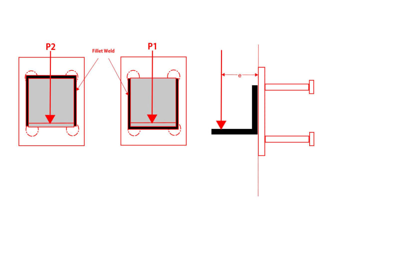
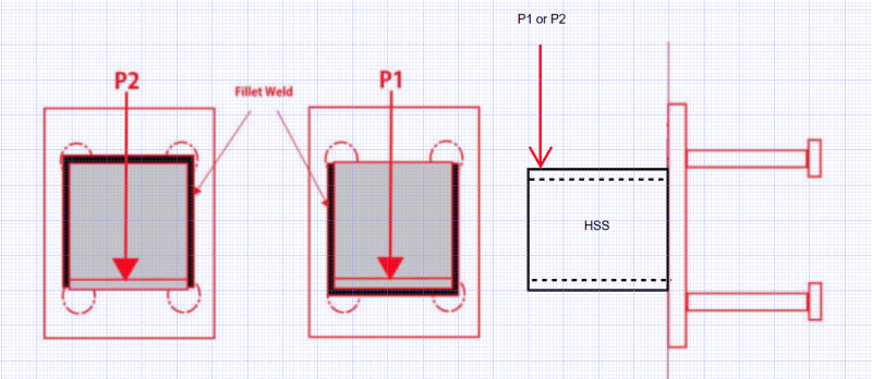
If you allow compression bearing development:
P2 will always result in the higher capacity. Correct
If you do not rely on compression development between the beam and embed and define failure as weld rupture:
P2 and P1 have equal design capacity. Perhaps, but how many engineers would do that?
P2 is ultimately a safer condition because after you reach the failure criteria of the vertical weld lines in compression you then have the additional redundancy of the compression bearing development creating an additional load equilibrium condition. Indeed!!