Continue to Site

Eng-Tips is the largest engineering community on the Internet

Intelligent Work Forums for Engineering Professionals

  • Congratulations cowski on being selected by the Eng-Tips community for having the most helpful posts in the forums last week. Way to Go!

Welding Capacity Calculation 7

Status
Not open for further replies.

JohnRwals

Structural
Jul 8, 2020
151
Hello!

P1 and P2 have exactly the same conditions except top, bottom horizontal welding.
I thought P2 could support greater vertical load.
But...
Which one do you think can support greater load? Why?

Thanks!

JW
R
Welding_Capacity_otqiin.jpg
 
Replies continue below

Recommended for you

Thank you, chris3eb. You have said it better than I. I interpreted the OP's question to be about capacity before failure.

BA
 
chris3eb,

I've not check the number yet, but both cases do have the component of compression, as long as the rotation is not about the bottom most edge of the angle. And, the compression is due to metal against metal, which turns out to be the bearing below the neutral axis/axis of rotation.
 
BAretired

So the stress distribution on your picture you have all the welds in tension except were the heel of the angle is, which apart from the fact that it is an assumption, you also claim it’s equivalent to a fillet weld in compression?
But according to AISC, Blodgett, Steel Construction Manual and several others using the elastic method, then the weld is subject to both compression and tensile stress.
Guess I won’t be writing to them to say they are incorrect.


“Do not worry about your problems with mathematics, I assure you mine are far greater.” Albert Einstein
 
desertfox,

BA's approach is counting the welds above the neutral axis only. Thus the couple is the effects from tension on the welds, and the plate bearing (compression) from below. I think it has merit for further look, but not for design.
 
r13,

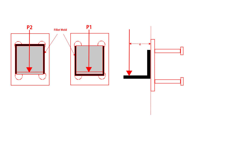
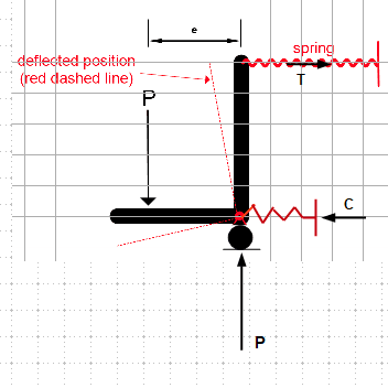
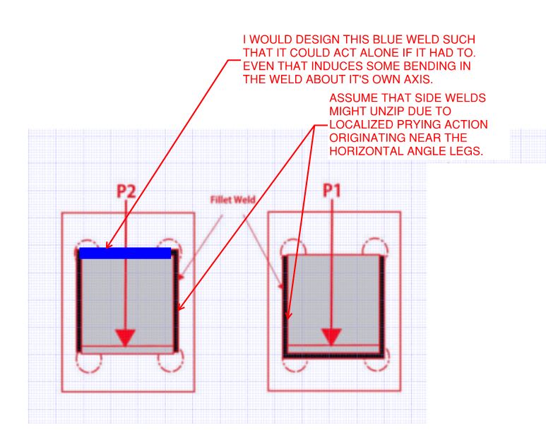
In P1, there is certainly no tension between the top of the angle and the plate. In P2, there may be some compression between the bottom of the angle and the plate - that is the extra capacity I am referring to.

desertfox,

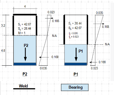
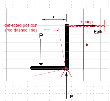
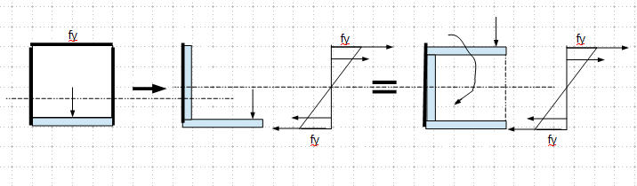
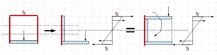
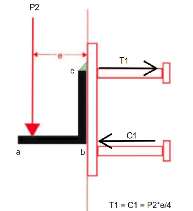
I agree that the last diagram posted by BA is incorrect. Using the assumptions he previously mentioned, the vertical welds should be half in compression and half in tension. With his method, the angle would act the same as if it had four welds when resisting moment (but only 3 resisting shear). I think most are in agreement that the design capacity would be the same - BA mentioned that a couple of days ago. If these angles were load tested to failure, do you think that P2 would hold more load? If not, is your thought that by the time any gap closed up, the welds would already be past the point of failure?
 
desertfox, r13:

I was simplifying it as shown below. All welds above the hinge would be in tension.

image_pzei1f.png


BA
 
This is what I was describing. There is a compression component in each case.

image_fgtzto.png
 
Hi chris3eb

In truth if we are looking at destroying the joint the only way to find the ultimate load would be a mechanical test and I don’t doubt that configuration P2 would probably be the stronger.
That said welded joints are complicated to analyse but the joint as to be designed in the first place and there may be lots of reasons why configuration P1 might be required. Using the elastic method as previously stated would mean either configuration designed for a given load would work with no issues. Even if P1 cannot benefit from an assumed bearing compression it on doesn’t make it a poor configuration if designed correctly.
What I also said is that it is better to use the elastic method and size the weld on the weaker Z value, therefore ensuring no working failure on the joint but if that joint configuration can benefit from some (assumed)bearing compression then that would be an added bonus. The problem I foresee designing it on what BAretired posted earlier is that the weld size would be under estimated and thereby fail in service.


“Do not worry about your problems with mathematics, I assure you mine are far greater.” Albert Einstein
 
We really have become bogged down in a lot of garbage brought on by a nonsensical stipulation that we cannot bear metal against metal without having a weld. We do it all the time with beams on bearing plates. The sensible thing to do here, instead of adopting the 'U' shaped weld configuration is to place one weld on top of the angle designed to resist P*e/d and allow the bottom of the angle to bear, without a weld against the embed plate. For those who are afraid we may have a gap, feel free to add a thin strip of steel between the angle and the plate. In my view, that would be a waste of time and effort.

A weld across the top of the angle will have a unit tension of Pe/bd and a unit shear of P/b. One simple weld should do it.

BA
 
BAretired

It’s not nonsensical that we cannot assume no bearing compression, all the references for weld design don’t consider it. If of course you have some information that we aren’t aware of that allows the calculation to be done with bearing compression please share it. Even chris3eb agrees your stresses on the weld all being in tension are incorrect. If you do this calculation all the time then show us a good example with values of stress and we can all benefit.


“Do not worry about your problems with mathematics, I assure you mine are far greater.” Albert Einstein
 
desertfox,

I too disagree with the assertion that the stresses in the vertical welds will be all tension; because the heel will move slightly as the angle compresses against the embed plate, causing a small compression at the bottom of the vertical welds. But it is close to being true. Neither your assumption nor my assumption is perfect but there isn't enough time to perform a finite element analysis on every angle welded to an embed plate. I believe my assumption is better than yours, but I would agree that, when in doubt, be a little conservative. With the inverted 'U' configuration, I would design the top weld to resist Pe/d on its own, without relying on the vertical welds.

In my last post, I suggested confining the weld to the top of the vertical leg of the angle and allowing the bottom to bear against the embed plate. The bottom support is simply a horizontal reaction. The lateral movement is trivial and does not affect the force carried by the top weld.

BA
 
BAretired

No principles that we use are perfect and of course that’s the reason for the safety factors and I agree that neither of us are perfectly correct. My only standpoint was that the joint needs to be designed in the first instance and all the researching I have done appears for the purpose of design, to use the elastic analysis and assume that all the force is transferred via the weld to the adjoining metal. I have attempted to calculate the stresses in the welds assuming that the U section weld in the configuration of P2 is rotating about its bottom edge where there is no weld.
All the welds are in tension and the maximum shear stress occurs across the horizontal weld at the top but sadly the magnitude of the stress is three times smaller than that found using the elastic analysis. I don’t doubt that there is a benefit from bearing compression and that configuration P2 is the more likely to benefit from it but I would prefer not to assume it’s there in the design but get it as a bonus.

“Do not worry about your problems with mathematics, I assure you mine are far greater.” Albert Einstein
 
Looking back at the example in Steel Construction Manual, the applied force P appears to be at an angle to the vertical. I assumed it was intended to be vertical, but I could be mistaken. In any case, to ignore the horizontal force at the bottom centre of the plate is certainly conservative, but it is wrong. To determine weld stresses without taking that force into account is pure fiction.

image_vziva7.png


BA
 
Yes in that picture the force was meant to be angled and I think if you follow the example through it accounts for the rotation of the bracket too, it was just an example I found which was close to what we were discussing.

“Do not worry about your problems with mathematics, I assure you mine are far greater.” Albert Einstein
 
BA,

If I didn't misunderstand, this is what you are advocating - for weld design, the geometric property of the angle is the same as the channel, or a tube, with the same member width and depth, due to contribution of the bearing; so the weld size should be determined accordingly. I wouldn't say it is correct or wrong, but it complicates the weld design process, for loading conditions that are largely dependent upon the geometry center/location of the neutral axis.


image_tvuypr.png


If the sketches do not catch your idea correctly, you should provide an numerical example, that reflects your concept, and people can understand correctly.
 
For me, from a design perspective, P1 actually has zero capacity as shown below. That said, I would normally specify welds both top and bottom.

C01_scsnwd.jpg
 
r13,

What I am advocating is a single weld at the top of the vertical leg of the angle...period. I showed it before, but repeat it here; the fillet weld is shown as a little green triangle at point c.

This is the simplest arrangement and makes maximum use of weld metal. Horizontal weld shear is T1 = P*e/d. Vertical weld shear is P. The horizontal reaction at point b is C1 = T1 = P*e/d where d is the vertical leg length (less a negligible amount to provide bearing).

Thin shims could be tacked to the embed plate at point 'b' to ensure the angle did not hang up on accidental projections, but I don't believe that would be necessary.

image_eh5wi3.png


BA
 
Status
Not open for further replies.

Part and Inventory Search

Sponsor