Continue to Site

Eng-Tips is the largest engineering community on the Internet

Intelligent Work Forums for Engineering Professionals

  • Congratulations cowski on being selected by the Eng-Tips community for having the most helpful posts in the forums last week. Way to Go!

Welding Capacity Calculation 7

Status
Not open for further replies.

JohnRwals

Structural
Jul 8, 2020
151
Hello!

P1 and P2 have exactly the same conditions except top, bottom horizontal welding.
I thought P2 could support greater vertical load.
But...
Which one do you think can support greater load? Why?

Thanks!

JW
R
Welding_Capacity_otqiin.jpg
 
Replies continue below

Recommended for you

First time done limit state based weld calculation. Please advise for mistakes, if any.

image_eaei5w.png
 
No mistake, r13 other than the assumption of no direct bearing at the bottom. T1 alone provides a moment M = 4Fy*4 = 16Fy when direct bearing is considered. The question the OP asked was:

JohnRwals said:
Which one do you think can support greater load? Why?

I think I have answered that question, notwithstanding opinions to the contrary.

BA
 
desertfox said:
So by assuming that the weld only carries the load for either configuration is a more conservative calculation, further if there is no direct bearing as the last poster steveh49 alludes to then you could end up with at joint that fails.

In a way, it is not more conservative because it puts an extremely poor detail, P1, on a par with an extremely good detail, P2. Failure is far more likely to occur with the former than the latter.


BA
 
BAretired

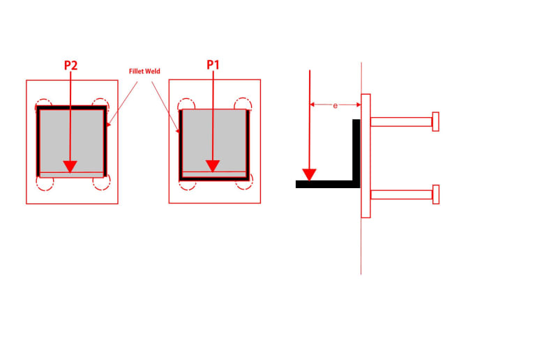
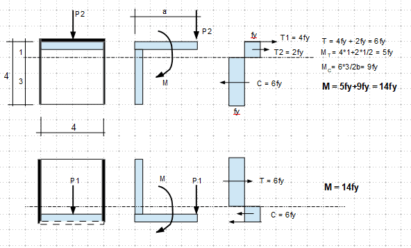
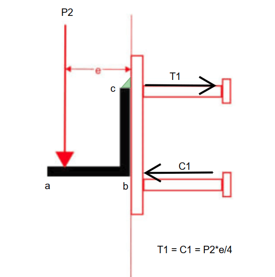
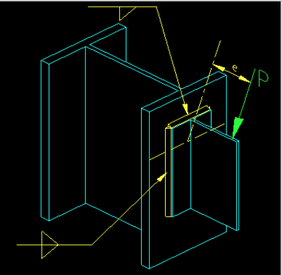
I disagree totally with you there, if you calculate the Z values on either side of the neutral axis for configuration P1 or P2 the overall Z is the same however the lower value of Z is the one above or below the neutral axis without the horizontal weld, so you would size the weld on the lower value of Z, that in turn ensures that the weld is adequate on the weaker side of the joint and keeps the stresses well within the allowable. I would rather design on that basis than assume something you can’t guarantee (bearing compression)and run the risk of over loading a joint.
Doing it using the elastic method ensures that the joint is safe and if there was any bearing compression to be had, then that would be a bonus. It’s worth noting I have never seen any codes or specifications that take into account bearing compression in welded joints.

“Do not worry about your problems with mathematics, I assure you mine are far greater.” Albert Einstein
 
To answer the question correctly it should be the one with the most conservative design, which in this case would be the elastic method and not assume benefit from a bearing compression which cannot be guaranteed.


“Do not worry about your problems with mathematics, I assure you mine are far greater.” Albert Einstein
 
BA,

At the case for P1, wasn't there a force of C1 = 4fy (see sketch). With or without weld, the compression was counted. I am confused on your used of full member depth as the lever arm.
 
r13,

That is really what the disagreement has been about. It is not a theoretical disagreement as we all agree (I think) about the capacity of the weld when direct bearing is not considered. When direct bearing is considered, reactions T1 and C1 are separated by 4 units.

If the back surface of the angle or the exposed surface of the embed plate is not planar, the argument is that there could be bearing somewhere between b and c (see below). If that were the case, however, inspection should reveal a gap at point b, in which case steel packing could be added between the two surfaces. It is also true that, as P2 is increased, any gap at point b will tend to close.

image_nqhlkd.png


BA
 
Got you. It is more complicate than I thought.
 
Hi r13

I have copied an extract from the Steel Construction Manual see attachment it clearly states the calculation doesn't take account of any compression connection between mating parts, which as BAretired said is were we differ.
Also I have pasted the link to the site for reference.


“Do not worry about your problems with mathematics, I assure you mine are far greater.” Albert Einstein
 
desertfox,

We are in line with each other. The compression BA mentioned is something else, that is usually not considered in the weld design. Thanks for the reference, which is quite illuminating.
 
desertfox said:
image_jqif2a.png


The forces are considered to be resisted by the weld group without taking into consideration any contribution from the compression between the connected parts.

I might do the same, especially now after all this discussion, but if you were to ask me which would carry more load, the weld as shown on your sketch or a weld placed on the bottom, I think you know what my response would be.

BA
 
I guess this is the case some people has in mind.

image_avd0hz.png
 
there shouldn't be any line stress in the lower half the weld is only on three sides
Screenshot_2020-10-20_003926_xvkayt.png


“Do not worry about your problems with mathematics, I assure you mine are far greater.” Albert Einstein
 
desertfox said:
there shouldn't be any line stress in the lower half the weld is only on three sides

image_ouhuqm.png


But cheer up, desertfox. If the point load is rotated 180o, then P1 is the stronger configuration.

BA
 
The diagram I posted is illustrating the stress in the weld only, which is actually what I thought we were interested in for the elastic method.


“Do not worry about your problems with mathematics, I assure you mine are far greater.” Albert Einstein
 
BA,

Can you show the axis of rotation?
 
desertfox,
The diagram I posted is the stress in the weld, assuming the heel point is fixed against horizontal movement.

r13,
The axis of rotation is the heel of the angle.

JohnRwals said:
P1 and P2 have exactly the same conditions except top, bottom horizontal welding.
I thought P2 could support greater vertical load.
But...
Which one do you think can support greater load? Why?

I believe your instincts were correct. P2 can support greater vertical load than P1, provided that the heel bears directly against the embed plate.

If direct bearing at the heel is needed in order to safely sustain P2, it would be conservative but prudent to add weld across the heel, creating a closed rectangular pattern of welds as shown in the snippet from desertfox's reference.

image_sfnq5o.png


BA
 
I think that there are two different questions here:
[ul]
[li]Which connection has a higher design capacity[/li]
[li]Which connection has a higher actual capacity before failure[/li]
[/ul]

P2 almost certainly has a higher actual capacity before failure because there will be some amount of compression developed between the bottom of the angle and the plate (especially if you are defining failure as the angle falling down, not the first propagation of cracking in the welds). The problem is that you may not want to count on it for design for the variety of reasons brought up (gaps, compatibility issues, AISC doesn't do it that way). But given the choice, I would much rather use P2 since it does have some extra reserve.
 
Status
Not open for further replies.

Part and Inventory Search

Sponsor