Continue to Site

Eng-Tips is the largest engineering community on the Internet

Intelligent Work Forums for Engineering Professionals

  • Congratulations cowski on being selected by the Eng-Tips community for having the most helpful posts in the forums last week. Way to Go!

Simulating a datum center plane 2

Status
Not open for further replies.

semiond

Mechanical
Jan 9, 2011
176
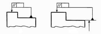
I need help in understanding this issue regarding simulating a center plane from a datum feature related to an external width dimension: let's say a width dimention is defined as a primary datum feature. When using a vise-like physical datum feature simulator with two almost parallel faces that close on the part, unless the tangent planes on both sides of the datum feature are perfectly parallel (and in the real world they're not), one of the vise faces will act similar to a primary datum plane - touching on 3 high points, and the opposite face will touch on only one point, similary to a tetriary datum plane. Now, depending on which side of the datum feature will make the more stable contact with the simulator, we might get a different separation width between the vise faces, and therefore the simulated datum plane will also be different. For example, if the measurement set up has the vise faces oriented horizontally, the side of the datum feature facing down will orient the part in the fixture, and if you flip the part upside down for a repeated measurement you might get different results on whatever control called out that datum. Now, I understand that there is only one "actual mating envelope" to the datum feature per ASME and only one of the sides facing down will produce the "minimum separation" condition per fig. 4-13, But that means that you have to mount the part twice in the fixtute and re-check your results, and I somehow doubt that this is the recommended practice... on the other hand, if the vise is oriented vertically, we will have no control over which side we stabilize better in the simulator - which is even worse. Everyone's insight will be much appreciated... Thank you!


Replies continue below

Recommended for you

pmarc,
Well, one can go further using one's own definitions, that's for sure.
I was staying closer to self-datum definition described in Krulikovski's "Advanced GD&T":
Now to my collection of pictures.
In the times of common sense there were simpler rule allowing you to:
Do not assign letter to datum feature if you don't have to:
Capture_1_mjaspe.png

To show that there is no difference, which feature to use as a datum and which one control:
Capture_3_g1dhf3.png

And simply say "those two to be parallel to each other":
Capture_2_vdq92b.png

Like I said, it's from my collection of pictures and tracing the sources may take extra time.

"For every expert there is an equal and opposite expert"
Arthur C. Clarke Profiles of the future

 
Old version of ISO 1101 has something similar to first one:
Capture_4_xyb03d.png


"For every expert there is an equal and opposite expert"
Arthur C. Clarke Profiles of the future
 
CheckerHater:

"5.4.4 Cylindricity
Cylindricity is a condition of a surface of revolution
in which all points of the surface are equidistant from a
common axis."

If the turntable of the cylindricity measuring machine does not rotate around a fixed axis, how do these machines do their job?
 
Think about measuring runout several times around different axes.
The smallest value will indicate that you found feature's own axis.

Once again - cylindricity - using it's own axis
Runout - using axis of something else
Cannot be the same.

"For every expert there is an equal and opposite expert"
Arthur C. Clarke Profiles of the future

 
semiond,
The same concept is used to define the circularity:"5.4.3 Circularity (Roundness)
Circularity is a condition of a surface where
(a) for a feature other than a sphere, all points of the surface intersected by any plane perpendicular to an axis or spine (curved line) are equidistant from that axis or spine"

 
CH,
You did not answer my questions about what would be your own opinion about the differences between your shwon cases A and B.
 
There is no difference - they are both wrong.

"For every expert there is an equal and opposite expert"
Arthur C. Clarke Profiles of the future

 
CheckerHater said:
Think about measuring runout several times around different axes.
The smallest value will indicate that you found feature's own axis.

That's good to know. But once the machine finds the feature's own axis, it checks the cylindricity value while while rotating the part around this axis isn't it? So why saying that "cylindricity has no axis"?

CheckerHater said:
Once again - cylindricity - using it's own axis
Runout - using axis of something else
Cannot be the same.

This is why in your fig.B where you showed total runout around the feature's own axis, you actually showed cylindricity. My point was that since this kind of callout has it's own definition, it is not recognized by the standard. Not because it is "self-referencing".
 
Cylindricity does not require the identification of an axis. Using one in auxiliary equipment can make verification simpler, but it's not required.

Runout does require an axis to be inspected.
 
This thread has sooooo many side discussions.

Anyway, cylindricity (and circularity for that matter) implies that all points of the surface to be equidistant from a common axis and does not say that that specific axis to be the datum axis or axis of the UAME.

Any axis is good enough.

After all, this control is *only* a form control. So, that cylindrical (correction)--total width-- tolerance zone (two concentric cylinders) can be optimized until you can get all the points of the surface within the tolerance zone specified. (In a similar way we should optimize the total width between two planes tolerance zone for flatness).
 
3DDave, even if the part is inspected for cylindricity by scanning of the surface in CMM and not rotated, still after all the calculations done by the machine, the end result of the control should be in line with what the standard defined - "all points of the surface are equidistant from a common axis."

Once again, i'm not implying that total runout is the same as cylindricity. What i said is that CheckerHater described cylindricity in fig. B of his sketch - not runout.

(For 3DDave only - I edited the post because i had typos, i type on my phone and it's a bit challenging with the small touch keyboard. I do go over it before pressing submit but i usually miss something and see it later, that's about it so don't bother looking in the previous versions).
 
semiond said:
What i said is that CheckerHater described cylindricity in fig. B of his sketch - not runout.
I do not know if that is true. In CH's skecth case B the datum axis A is derived from UAME (Unrelated Actual Mating Envelope) of the cylinder versus --as I stated above---cylindricity does not require a specific axis and can be any axis.

Any disagreements with my statements?
 
3DDave said:
If parallelism is to be controlled - pick one surface as a datum reference and apply the tolerance to the other - no need to sum the results and very easy to inspect.
This is something i consider doing to qualify the primary datum feature of width. But that means that a 4th datum should be defined in addition to the 3 datums of the datum reference frame. I'm trying to find other solutions first.
 
Greenimini, i agree with your statement but not with your implied conclusion (that in CH's sketch fig. B does not describe a cylindricity control in disguise to "self referencing" total runout).

It is apparently true that the axis that the standard mentions in the cylindricity definition is not necessarily the axis of the AME, but it doesn't mean that it can't be.

For example, one of the most commonly used devices to establish the AME of a cylindrical surface is a prism. Can a prism constrain a cylinder while it is checked for cylindricity? I think yes.
 
semiond,
Do you understand difference between parallelism and flatness? One has datum, another doesn't?
Well, it's the same. Cylindricity is runout without datum. If it has datum, it's not cylindricity.
End of story.

"For every expert there is an equal and opposite expert"
Arthur C. Clarke Profiles of the future

 
semiond said:
It is apparently true that the axis that the standard mentions in the cylindricity definition is not necessarily the axis of the AME, but it doesn't mean that it can't be.

See my replay from 15:04 (optimization) with the following addition:

If axis of UAME does not make all points of the controlled surface fit into the tolerance zone, you can find another arbitrary axis to do just that.
The point of optimization is to find the place that works, not to demonstrate the plethora of places that don't work.


semiond -

What three datum references? Your initial problem had only one and your complaint was that it was based on an unreliable datum feature on the part and therefore giving unreliable results. Now it's four?
 
3DDave, you weren't following some my prevoius posts. In that sketch i only showed one incomplete view of the part, just to make a point about the center plane simulation technique and the error that might be caused.
There are other features on the part: central bore, keyslot and a pattern of holes.
 
I find it interesting what pmarc is claiming:
“I am saying that your case B is not self-referencing. Why? It is because datum axis A is derived from UAME (Unrelated Actual Mating Envelope) of the cylinder, and the total runout itself controls condition of the surface of the datum feature.”

I understand it, but I am wondering how many GDT users will be deceived into the trap of thinking that is self-referencing.

Fig. 9-7 -2009 shows a controlled outside diameter (named datum feature D) with runout within 0.05 to C primary and D secondary and here I understand that the datum axis is the axis of RAME instead of UAME. So it is not self-referencing. But pmarc’s example I am more inclined to say it is.

Now, the natural question is:

What means self-referencing? Pmarc gave us his definition: “My definition of datum self-referencing is that self-referencing is when inspection reading of a geometric characteristic defined relative to a datum is always 0, no matter what, just like in the case I described yesterday - width chosen as datum feature C and then its center plane controlled with parallelism tolerance to the C. The measurement result will always have to be 0.”

Seems logical. However it is not defined in the standard. Another "unless otherwise specified" to be?
 
Status
Not open for further replies.

Part and Inventory Search

Sponsor