Continue to Site

Eng-Tips is the largest engineering community on the Internet

Intelligent Work Forums for Engineering Professionals

  • Congratulations 3DDave on being selected by the Eng-Tips community for having the most helpful posts in the forums last week. Way to Go!

Hex hole as a datum feature

Diametrix

Aerospace
Jan 31, 2023
54
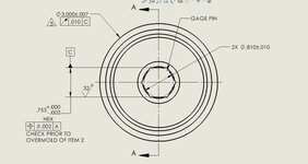
I know you can use a square hole as a datum feature - put a single dimensions with a square symbol and attach a datum symbol to it. Can you do the same for other geometries as well? With the square you define two planes of symmetry which form an axis at their intersection. With other geometries they either form multiple axes or they don't form a plane at all (like in a case of a triangular hole). I understand the intent here with the gauge pin used to establish the datum, but I'm not sure that it jibes with the standard.

Roller.jpg
 
Replies continue below

Recommended for you

Seems to me like it would be acceptable were it not for the gage pin bit, which I don't understand why they would ever include that. Just makes it confusing and ambiguous. Datum C as sets of parallel planes makes sense. Like creating a datum from the length or width of a rectangular slot.
 
It looks like the design intent is for the hex drive to define the axis of datum C, from which the runout of the 3.0" diameter can be measured. While that can be inferred, there's probably clearer ways to define it. Otherwise, I see no issues with the concept of applying the datum to the hex flats, but that specifically makes more sense to me when angular orientation is important.
 
It looks like the design intent is for the hex drive to define the axis of datum C, from which the runout of the 3.0" diameter can be measured. While that can be inferred, there's probably clearer ways to define it. Otherwise, I see no issues with the concept of applying the datum to the hex flats, but that specifically makes more sense to me when angular orientation is important.
I'm not altogether clear on how it works. With 6 sides we define three center planes, which for the real parts will not intersect at the same axis. So we would have 3 separate axes. Which one do you use as the datum axis? In addition, what happens if the hole has odd number of sides, can you still define it like that?
 
Since the datum feature reference callout is RFS, then an expanding plug would be used and the center of that plug is the datum axis. Unless the mating part is also self-expanding the installed condition isn't going to match whatever inspection reports.

It would be equally useful to declare the outer diameter (OD) as a datum feature and have three pairs of surfaces with a position tolerance controlling them to the axis of OD datum feature. This would indirectly control runout due to the offset of the surface parts from the axis of the contracting cylinder around the OD of the part. Instead of runout, the OD would be controlled with cylindricity geometric characteristic control.
 
I'm not altogether clear on how it works. With 6 sides we define three center planes, which for the real parts will not intersect at the same axis. So we would have 3 separate axes. Which one do you use as the datum axis? In addition, what happens if the hole has odd number of sides, can you still define it like that?
I think that the CMM will do a best fit to determine the center axis.
 
The datum feature symbol is aligned with the .753+.000/-.002 width of the irregular hexagon. So, if this drawing is to be interpreted by any internationally known standard on dimensioning and tolerancing such as the ones by ASME or ISO, datum C is the center plane of this specific internal width. It is unrelated to the other faces of the irregular hexagon, and the fact that there is a GAGE PIN note shown separately doesn't change the interpretation either.

There is no datum axis, and a Runout requirement relative to a center plane is meaningless.
Never mind. I agree about irregular feature of size. However, irregular feature of size can still be a datum feature. The .753+000/-.002 dimension is applied to the distances between all matching parallel surfaces of the hexagon based on the HEX note, which creates a set of three center planes as a datum C. What am I missing?
 
Last edited:
What is an "irregular hexagon"? Are you trying to say that the hexagon is an irregular feature of size? Based on 14.5Y definition it is a regular feature of size. The .753+000/-.002 dimension is applied to the distances between all matching parallel surfaces of the hexagon based on the HEX note, which creates a set of three center planes as a datum C. What am I missing?
Diametrix, are there other features on the part which define angular orientation? I'm guessing not because it looks like a simple threaded plug. Otherwise, if datum C is only 1 pair of opposing flats (per Burunduk, and as I also initially thought), you'll never know which of the 3 pairs it is. 3 people could inspect the part and set it up differently on the 3 different pairs of flats. I agree that the HEX note adds something and indicates that the linear dimension applies to all three pairs of flats. I think that the gauge pin note also implies that the axis of the pin should be used as the datum, but that might not align with the "official" interpretations according to the standards.

There is another potential problem here. It appears that the hex is broached into the part after a 0.810" pilot hole is drilled. This means that the flats will not be complete. The middle material will be missing. Only the 6 vertices/corners will have the actual flat. This works fine for driving the part by a hex key, but it does not facilitate inspection of the part's flats. It will be challenging to register any gauge confidently to the flats. Any gauge pin used will not touch the 6 hex flats (theoretically), but will actually touch the pilot hole diameter. It appears to be drawn with a different expectation, as the gauge pin diameter is aligned with the flats. Is there a section view available on the center axis of the part?

Is it correct that you are not the designer of the part, but rather the inspector of the part?
Correct, it's not my drawing. As for the flats of the hex, the view that I sent is somewhat misleading. Think of a set screw with a hex socket. Here is an isometric view.
1748611010774.png

No angular orientation dimensions on this drawing. It seems ok though as is. Parallel sides are defined by implied zero and vortices are sitting on the center line. I suppose the shape form can be misinterpreted based on the fact that the angles are not defined explicitly. However the note HEX means a hexagon, which by definition means a six-sided polygon with internal angles equal to 120 deg.
 
Last edited:
Since the drawing clearly says "HEX," I think it's clear that the datum is intended to be created from the full six sides, not just the two flats being pointed to.
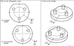
In the ASME Y14.5 standard, Figure 7-3 shows two interesting examples at the bottom of that graphic. Although they are rounded, not hex or rectangular, could there be a way to extend those concepts to the hexagon? The datum could then be a combo of an axis and a plane, much like their example (f).
 

Part and Inventory Search

Sponsor