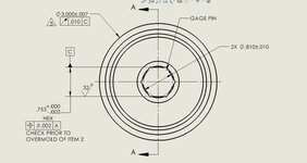
There are ways, not implemented in the OP's image, to indicate that the entire hexagon shape is to be treated as a single geometric entity (feature or a pattern of features) to control and derive a datum from. The datum would be an axis and a plane, since the shape qualifies as a "linear extruded shape" - figure 7-3 (f) in ASME Y14.5-2018 as noted by Garland in post #11:

As I mentioned, the conclusion that it's a regular hexagon per-design should not be automatic and it needs to be indictated by proper dimensioning. The note "HEX" doesn't really add useful information because anyone looking at it can tell it's a HEX(agon), but slight differences in widths across flats that may be there per-design may not be visually distinguishable.
Two examples on how to control the Hex's size, form, and relationship to other datum features, and indicate it as a datum feature, are:
1. The current scheme shown in the OP's post, including the position tolerance, but without the diameter symbol preceding the tolerance value and with the addition of "3X" before the size dimension (a "HEX" notation doesn't create a pattern, the "nX" indication does). Also, for a full drawing-only based definition, 6X120° basic has to be explicitly specified (unlike 90° or 0°/180°, basic 120° angles are not implied).
This method treats the hex as a pattern of 3 widths and will require measuring and reporting:
- total of six size values: 3 maximum-detected actual local sizes, across the 3 pairs of flats, to ensure the LMC limit of .753 is not violated, and 3 unrelated actual mating envelope sizes (max. inscribed widths) to ensure the .751 MMC limit of size and form (rule #1) boundaries are not violated on any of the 3 pairs of flats.
- three measured position values for the 3 center planes across flats.
2. Another possible scheme is giving 3X basic width dimensions between flats and basic 3X120°, and applying profile of a surface to the hex all-around, similar to how it is shown in figure 7-3 (f), but with the appropriate datum references (in a scenario closest to the given one the profile FCF would reference A and the feature would be labeled C).
This method treats the Hex as a single feature and controls directly the 6 surfaces that form it. It requires measuring and reporting only the actual profile value to qualify the hex. An advantage over the first method is likely less effort and a shorter inspection report. A drawback is the unexplained bias against profile and the tendency to tag it an "overkill".
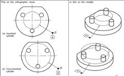
Another method to define the datum axis for runout from the hex could be by a principle similar to the shown in the following figures:

This is the standardized way to invoke the mentioned gage pin mating with the feature.
An issue would be, when applied to a hex geometry, you wouldn't know which 3 surfaces are in contact with the datum feature simulator pin (this is related to what 3DDave mentioned). The pin must be expandable or the largest that fits since the datum reference for runout can only be referenced at RMB.


