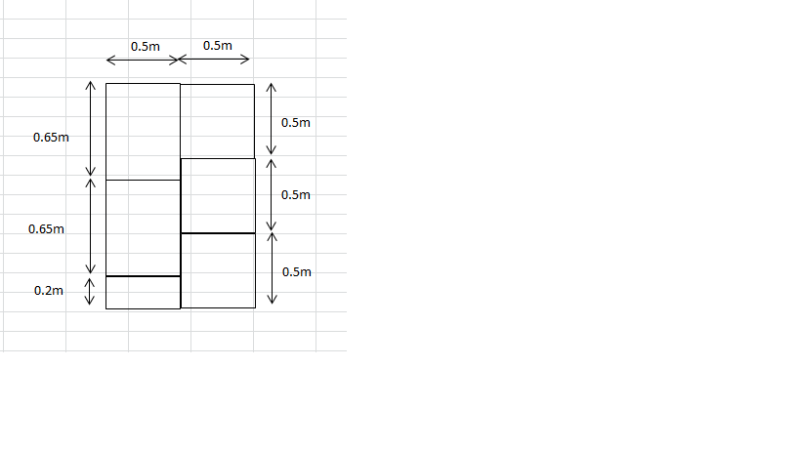
I'm going to take a wild guess here, and assume that:
1. You want to analyse an RC floor system supported by beams (probably modelled with plate elements, with line supports representing the beams.
2. You're worried that it won't mesh properly. I.e. each of the rectangles will have their own "mesh" pattern, with "nodes" that don't link up between adjacent panels.
As others have said, you need to be sure in what you want to analyse. Are they one single monolithic slab, or individual slabs? This is going to be extremely software specific, but any decent package will ensure this is something you don't need to worry about for something simple like this ; although the mesh will look terrible, with a very poor aspect ratio).
Yes, the nodes need to connect; the "mesh" is the structure/model, the geometry on which is based isn't considered in the analysis at all. I think understanding the difference between "geometry" and "mesh" in FEA-land will be helpful, going through the manual will be a helpful thing for you to do. Fundamentally, FE is the subdivision of a very large structure into very small pieces (or "elements", connected at individual points (or "nodes"). (please don't burn me at the stake if this statement isnt 100% correct

, yes I know you can have additional nodes in between etc). If these pieces are not connected, they will act independently.
Hope this helps (also I have some sympathy, as resident FE-guy I have a lot of experience dealing with grads fresh out of uni/college who at best, go through the worked examples, at worst not even that in terms of experience). gl!


