Continue to Site

Eng-Tips is the largest engineering community on the Internet

Intelligent Work Forums for Engineering Professionals

  • Congratulations KootK on being selected by the Eng-Tips community for having the most helpful posts in the forums last week. Way to Go!

FEM MESHING OF PLATE

Status
Not open for further replies.

allimuthug

Civil/Environmental
Oct 5, 2014
142
Hi

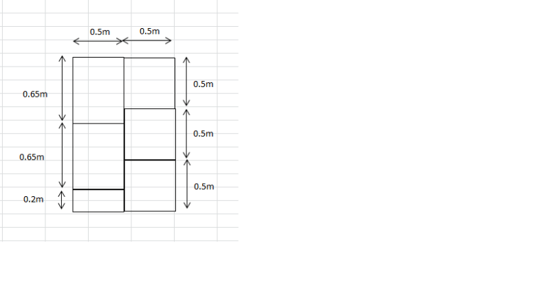
I have a plate element, which is meshed as shown in the picture given below. Is that a right way of meshing. If not can anybody give a good reason.
If I am having a slab of 7 meter x 12 meter x 650mm thick and going to analyze as a plate element, what is the size of mesh I have to use. Please explain about aspect ratio of plate mesh in detail.
FEM_xtugvu.png
 
Replies continue below

Recommended for you

is that the complete mesh ? so the corners of the elements (the rectangles) don't align ? is so the mesh should fail (because it is not continuous).

it is not clear what your structure is, nor why you've chosen to idealise it the way you have.

another day in paradise, or is paradise one day closer ?
 
I just shown an example, I just want to know weather the plates must me connected only to the nodes, why not as shown in the above sketch.
 
Hi
I don't understand your figure. Does your complete mesh consist of six elements?

The elements need to be connected at the nodes. This approach may be software specific but I don't think the mesh will work.

Thomas
 
ok, your example is very poor; particularly when you say "I have a plate element, which is meshed as shown".

1) it lacks continuity
2) the mesh is very coarse
3) we don't know where the loads are, where the constraints are, where the limitations of the structure are, where things are that'd affect the mesh, ...

it would be more useful to post the structure you're trying to model and say "how'd i do this?".

expect a bunch of replies like "go back to school and learn FEA" or "hire a component SE".

another day in paradise, or is paradise one day closer ?
 
Why don't you just create the mesh as you have sketched it, and see what happens?

And then generate another mesh where all of the elements join at common corner nodes.

This would be a useful self-education exercise for you to undertake over the holiday period, and then check back in here in the New Year if you have any further questions.

Happy Holidays everybody!

 
Quoting:

> I just shown an example, I just want to know weather the plates must me connected only to the nodes, why not as shown in the above sketch.

Your sketch shows no connectivity b/w the elements, meaning that you will have a severed load-path or no load-path at all.

Also learn how to spell /whether/.
 
what u are showing in the picture is not consistent with your description of the slab. it is one slab or six slabs. are they individual slabs or they are bonded together which acts as one piece. and the dimensions that u are describing doesn't not match the dimensions in your picture.

disclaimer: all calculations and comments must be checked by senior engineers before they are taken to be good.
 
I'm going to take a wild guess here, and assume that:

1. You want to analyse an RC floor system supported by beams (probably modelled with plate elements, with line supports representing the beams.
2. You're worried that it won't mesh properly. I.e. each of the rectangles will have their own "mesh" pattern, with "nodes" that don't link up between adjacent panels.

As others have said, you need to be sure in what you want to analyse. Are they one single monolithic slab, or individual slabs? This is going to be extremely software specific, but any decent package will ensure this is something you don't need to worry about for something simple like this ; although the mesh will look terrible, with a very poor aspect ratio).

Yes, the nodes need to connect; the "mesh" is the structure/model, the geometry on which is based isn't considered in the analysis at all. I think understanding the difference between "geometry" and "mesh" in FEA-land will be helpful, going through the manual will be a helpful thing for you to do. Fundamentally, FE is the subdivision of a very large structure into very small pieces (or "elements", connected at individual points (or "nodes"). (please don't burn me at the stake if this statement isnt 100% correct ;), yes I know you can have additional nodes in between etc). If these pieces are not connected, they will act independently.

Hope this helps (also I have some sympathy, as resident FE-guy I have a lot of experience dealing with grads fresh out of uni/college who at best, go through the worked examples, at worst not even that in terms of experience). gl!


Status
Not open for further replies.

Part and Inventory Search

Sponsor