Continue to Site

Eng-Tips is the largest engineering community on the Internet

Intelligent Work Forums for Engineering Professionals

  • Congratulations waross on being selected by the Eng-Tips community for having the most helpful posts in the forums last week. Way to Go!

Wood Guys - This a Problem? 4

Status
Not open for further replies.

azcats

Structural
Oct 17, 1999
693
***I'm wholly unaffiliated with this project***

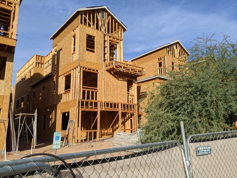
Driving home over the weekend and saw these condos under construction. Thought the framing was interesting so I stopped for a look.

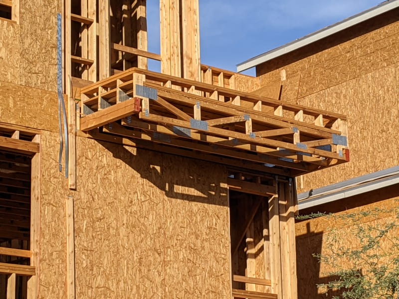
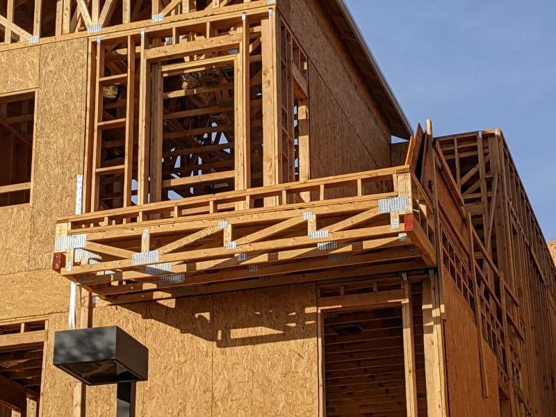
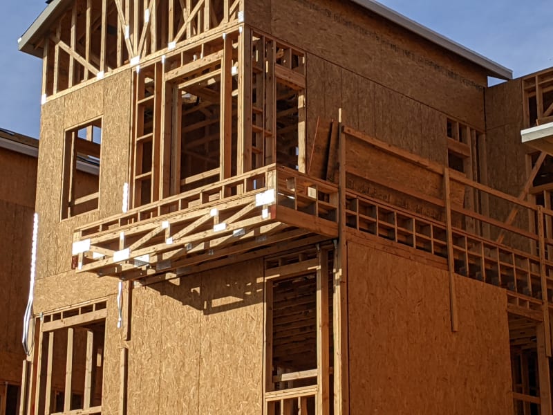
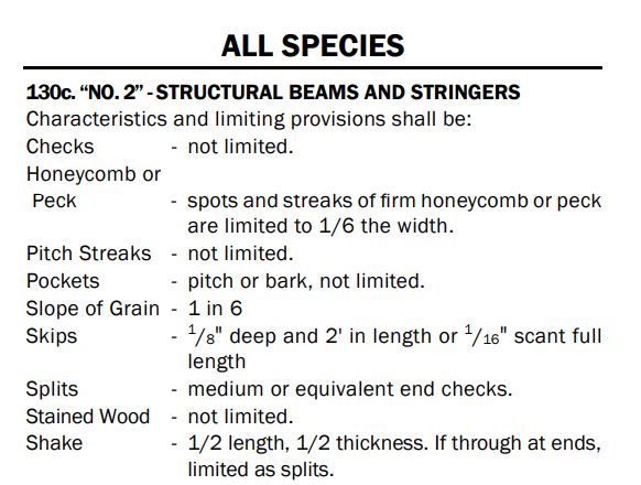
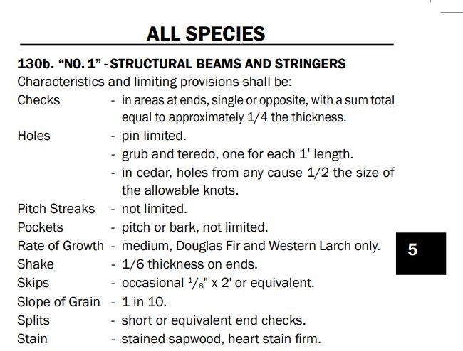
Any concern with the checks/splits in those cantilevered 4x8s? Or is this already considered in the lumber grading?

PXL_20201121_222911397_wdyorh.jpg

PXL_20201121_222936597_gn87dj.jpg

PXL_20201121_223021513_o68cjq.jpg

PXL_20201121_223103601_y0au8j.jpg
 
Replies continue below

Recommended for you

1) I believe that these would be the National Lumber Grader's Association specifications for this.

2) No limit at all for #2 or lesser.

3) In my opinion a more reasonable limit for #1 and better.

4) One would think that "ends" would really be the high shear location at the start of the back span for a cantilever.

C01_tdaium.jpg


c02_cicx21.jpg
 
After checking on all referenced material, I find the contractor is quite experienced and smart in leaving the face with checks facing out, and leave the smooth (assumed) face inward to support the interior joists, and not violating the rule - not to glue or use strap to close the checks, for which may impede the wood from expand/shrink during the next drying cycles.

From KtooK's latest excerpt, can this 4x8 graded as No.1 lumber, with the checks near/at ends less than 1/4 of the thickness? Seems the check outside of the end region does not count towards grading.
 
The drainage on the top of the balcony doesn't matter. It looks like a t-bar drainage system on the balcony, but unless that's flashed incorrectly that doesn't matter either. The problem is that stucco is not waterproof and neither is the paint....water will get in there and without proper weeps it won't get out....thus the rot.

 
Of course the drainage on top of the balcony matters. It's a bucket of water otherwise. But, if what you're referencing is a lack of weep screed at the soffits then, sure, I take your point.

C01_ezay47.jpg
 
If it is a t-bar perimeter system on the balcony (which is common), the drainage is under the slab, not on top. Yes, you want most of it to run off, thus the conductor head, but there has to be waterproofing under the slab.

Yes, that's the type of weep to which I was referring.

 
I certainly close my eyes and trust the system. The Australian code simply limits the opening width (3mm) and length of the check (L/4 to L/2), but not the depth of the check. The depth just needs to be less than all the way through the stick. Got 1mm hanging on at one edge? That's a check, not a split. Check is fine for half the length; split of any length would be rejected. Internal checks are limited to 10% of the cross-section though. [ponder]

Moving to USA because you have more documents explaining code provisions, TFEC Tech Bulletin 2018-10 says "the tabulated allowable shear stresses [in the NDS] are based on the conservative assumption of the most severe checks, shake or splits possible, as if the timber were split through its full thickness for its full length." It also says there are limits on the depth of check for the higher grades which is more encouraging than the Aust requirements.

What I don't get is the reasoning behind only reducing the allowable shear stress because of the hypothetical full-length full-width check. That could halve the bending strength if located at mid-depth, whereas I picture two parabolic shear stress distributions that sum to the same as the single full-depth distribution. More than happy to be set straight here.


I suspect that the TFEC verbiage was not crafted with sufficient precision. A check that goes full width becomes a split and there are limits on splits which seem geared toward the preservation of horizontal shear capacity where you'd want it for composite behavior. So it's spurious to imply that there's such a thing as a full width check.
 
That (full length, full depth checks) could halve the bending strength if located at mid-depth,...

Why's that?
 
Because you'd be effectively assuming no horizontal shear connection between the upper and lower parts of the beam. No VQ/It shar flow stresses.
 
What I don't get is the reasoning behind only reducing the allowable shear stress because of the hypothetical full-length full-width check.

They reduced the allowable shear stress, means there is some shear stress passing through the checks (not completely lost). By limiting the shear stress, the span length and intensity of loading will be reduced as well, which in turn reduces its effects - moment and normal stresses.

I shall have highlight the word "halve". Thinking 2 4x4 stack together, what is the moment capacity - with limit set on loading, and without?
 
If you don't have shear flow, you essentially have a pair of 4x4s. Since moment capacity of a rectangular section is proportional to the square of its depth, a 4x4 would have 1/4 the bending capacity of a 4x8. Stack two 4x4s without a connection for shear flow, and the resulting stack has half the moment capacity of a single, solid 4x8. So long as the check is a true check as KootK describes (doesn't pass through the entire width of the member), there's a shear flow connection that allows the whole section to act together.
 
My fault, as I didn't make my point clear.

A 4x8 is rated to carry the shear due to 100 plf uniform load. Due to the presence of the seam (in mid height), the allowable shear is reduced to effect a 50 plf uniform load (by code). Does the code needs to further stating limit on the bending strength of the 4x8? No. My point is through "reduction" in shear capacity, the code has already reduced the moment capacity without the need to limit the consequent flexural stresses.
 
I'd agree with that. As long as your horizontal shear capacity at the check meets your horizontal shear demand, you've got the bending capacity that you were expecting in the normal way. I think that steveh39's thing was that, if you have NO shear capacity at mid-height because you've got full width air space there, then surely your bending capacity must be that of two independent pieces rather than that of a single composite piece.
 
This thread shall be carefully reviewed - Stacked Beams, Link

image_zbwl1h.png
 
r13,

In your last sketch (boards bonded together), the end slope should not be vertical.

BA
 
I think that this is a really bad construction detail/method. I won't go as far as saying that this is downright dangerous but it looks pretty bad. I've seen engineering drawings for wood frame buildings like this (especially multi-res) and the detail can be pretty lacking at times. It's usually just a slathering of joist/beam sizes, post locations, etc... along with a bunch of typical details. Some of the more complex framing gets overlooked at the builder has to 'wing it'. Scary stuff sometimes. Also worth noting is the fact that this building is using a floor truss system (instead of engineered joists or cut lumber). This can sometimes lead to a disconnect between the main structural consultant and the truss supplier. Quite honestly, the truss suppliers would be well-off paying their own engineers good money and just do up the whole structural system for the wood framing instead of the owners paying two separate firms to work against each other.

Framing residential housing with a wood truss system gets complicated quickly. The rim board (or rim truss or whatever they would call it in this case) highlights the extra complexity. The balcony framing still looks a little convoluted none the less. If the ceiling is the same height as U/S of balcony they could have simply cantilevered the floor framing out at least until the exterior wall over. The house on the left has the floor system cantilevering out but I think it has a different balcony. If the slope (for drainage) ends up being lower than the inside floor height they can still make a truss that accommodates for that without much additional cost (it's shop fab'd anyways). Maybe I'd understand their approach better if I saw the drawings; perhaps they didn't want a beam getting 'squished' by that corner post but there's not much load there anyways. If it were my house I would have really preferred to see a 3rd cantilever for some much needed redundancy. I don't quite get why the truss attachment at the bottom-right looks so flush/square and the bottom left looks so out of wack - it looks like somethings off there. They would have had to do something their prior to closing and installing the exterior finish (stucco?). The trusses look like there is no positive connection to the cantilever beams (maybe I missed something but hopefully it's not toe nails). Quite honestly I think they could have framed the balcony without trusses but I'd have to see the bigger picture. The cantilevers need a strap or some sort of hold down at the interior. Maybe it exists but is hidden by their temporary guard rail. Hopefully this is a very favorable climate. It would have been much wiser to go with an engineered product, or at least a pressure treated product (I forget how much weaker PT'ing makes wood though). A lot of the issues we're seeing on the wood could be due to weathering. Maybe it was really wet followed by a dry period.

My best guess is that the engineer came to site, saw this, and made them fix it up before they closed the building in. Unless that exterior finish is something special I think it's going to crack.

Just my disorganized thoughts...
 
I'm a bit late to the party here. Its been a record crazy month.

I spent a couple years around the old parts of town on the west coast doing alterations on existing timber framed buildings. They dont build them like they used to, thank god for that. I have seen timber do some pretty impressive things for an impressive amount of time.

Have seen more than a few sets of 18' long 2x4 roof rafters at 24"OC, on low slope roofs that have seen a century of winters.

2x4 stud walls balloon framed that have supported 3 levels of occupants - where the floor framing was notched 2" into the 4" depth of the stud. that have served as boarding houses/brothels/gambling dens since the 1800s.

Seen plenty of old houses where 3 levels of significant tributary area of framing will be bearing down on a single 4x4 post. resting on a 10" round rock as a footing.

None of these applications come close to meeting modern building code. But they demonstrated proof of performance.

This framing attached, even if it doesnt meet code, will survive. So long as the end of that cantilever is strapped down (which i didnt see).

And it doesnt matter how grunty your framing is, it will eventually rot out with a face sealed cladding like that shown, unless you are in the desert.


Status
Not open for further replies.

Part and Inventory Search

Sponsor