BAretired[/color]]
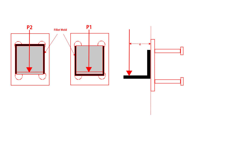
Cant see how you get Mmax for P2?
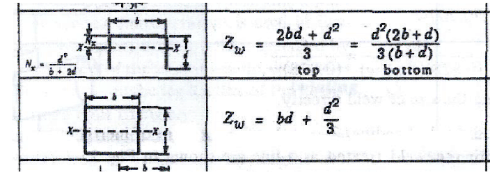
Looking in Mechanical engineers data by james Carvill the Z value for the weld treated as a line at position P2 is given by
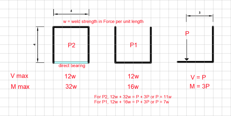
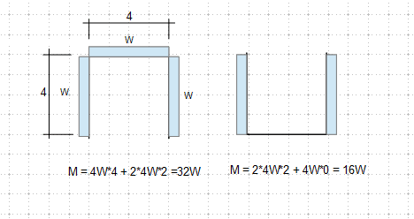
Z= (2bd+d^2)t/3 at the top . . If b = d = 4 then Zw = 16 (top of P2, ignoring direct bearing)
Z = bd + d2/3 top or bottom of P2, recognizing direct bearing . . Zw = 16 + 16/3 = 21.3
Z= d^2(2b+d)t/(3(b+d)) at the bottom . . Zw = 8 (top of P1)
Z = bending modulus, d = depth , b= width
So the bending modulus Z at the top and bottom are different as stated by others in previous posts, however it doesn't matter which way up you weld the the angle all that happens is the Z values top to bottom switch over but the overall capacity of the weld to take bending remains the same, which is exactly what Celt83 stated on the 12th October, or at least thats how I read it.