Hi dculpt1,
I've been thinking about his a bit and this may be redundant given some of the other advice you've received. But here are some things I would consider:
1. We know you are designing this for a fatigue application. That does not invalidate your static stress application though. For fatigue, we are not explicitly interested in the Kt (static stress concentration factor. Moreso we care about Kf, the fatigue stress concentration factor. That being said, the two are related via the notch sensitivity. So immediately you may be able to improve the performance by selecting a material with better Neuber constant, "a". Although you might be locked in. Furthermore, the notch sensitivity is also influenced by the radius.
You can also change the Neuber constant by changing conditions (annealed or strain hardened vs heat treated, etc).
2. Improvements to the local stress can also be made by introducing residual stresses. Shot peening has been discussed above. But there are many other ways to achieve this including:
-through hardening
- case hardening
-cold forming
-laser peening
-other methods of mechanical prestressing compressively in the axis you know the part is loaded in
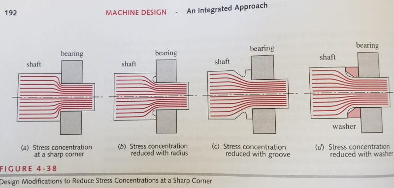
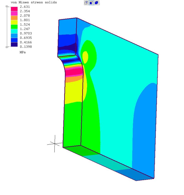
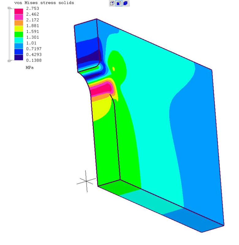
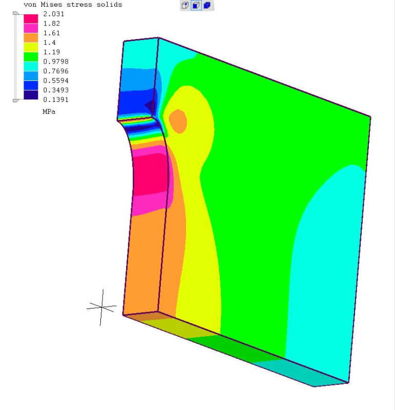
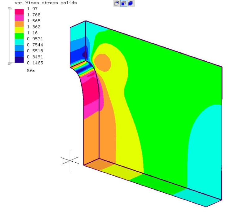
3. There are more ways to change the local stress field other than altering the tip radius. The "flow" analogy you mentioned is alluded to in this figure from Norton. It is not really what you have, but gives the idea.
The crux of the stress riser problem is twofold:
1. The reduction in net section area causes a higher stress because, well, the cross section is smaller
2. The eccentricity of the load path ie "flow" diversion causes some effective bending...think about the load path and the crystal lattice.
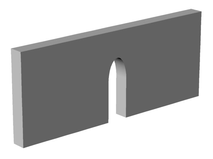
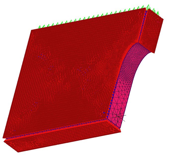
You could possibly mitigate Item 1 by providing more material to take the load. The notch tip causes a concentration, but this could be somewhat offset if the cross section was greater in that area. Is there any reason you cannot slowly ramp up the width or thickness to be greatest in the cross section of the notch tip?
Finally, you said you have Peterson... if it is the Pilkey version, have a look at Section 4.5.1, page 225:
Pilkey/Peterson said:
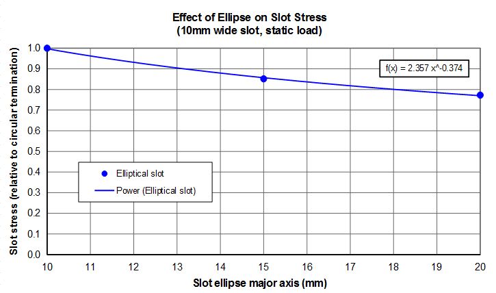
A photoelastic investigation (Durelli et al. 1968) of a slot of constant a/b = 3.24 found
the optimum elliptical slot end as a function of a/H9 where H is the panel width. The
optimum shape was an ellipse of a/b about 3 (Chart 4.59), and this resulted in a reduction
OfKtn, from the value for the semicircular end of about 22% at a/H = 0.3 to about 30% for
a/H = 0.1 with an average reduction of about 26%. The authors state that the results may
prove useful in the design of solid propellant grains. Although the numerical conclusions
apply only to a/b = 3.24, it is clear that the same method of optimization may be useful
in other design configurations with the possibility of significant stress reductions.
However, you'll notice chart 4.59 does not have the stress orientation you desire. That being said, there is a biaxial stress effect in Chart 4.55 which shows that the Kt will reduce when biaxial stresses are present. So you could also control the peak stress by introducing some other load.
Keep em' Flying
//Fight Corrosion!