Continue to Site

Eng-Tips is the largest engineering community on the Internet

Intelligent Work Forums for Engineering Professionals

  • Congratulations waross on being selected by the Eng-Tips community for having the most helpful posts in the forums last week. Way to Go!

Slot in plate - best end shape for minimum stress?

Status
Not open for further replies.

dculp1

Mechanical
May 16, 2006
75
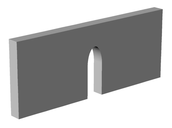
The image shows a plate with a 10mm wide slot. In this design the slot's end shape is a 20mm x 10mm ellipse. A uniform tensile load is applied to the plate's top surface (the narrow surface at the top of the image). Compared to a slot with an R5mm end shape, the von Mises stress is 23% lower.

Besides an ellipse (and possibly a polynomial), what other end shapes should I consider in order to minimize the stress? (I seem to recall a shape that approximated the surface streamline of a fluid flowing through an orifice but I haven't been able to find this again.)

Thanks,
Don C.
Slot_with_elliptical_end_1a_d2riw5.jpg
 
Replies continue below

Recommended for you

rb1957 --

The following reference may be helpful --

Wells, Joseph M.; Buck, Otto; Roth, Lewis D.; Tien, John K. (editors), Ultrasonic Fatigue, The Metallurgical Society of AIME, Warrendale, PA, 1982, ISBN 0–89520–397–9

I attended this symposium in 1982.

Much else has been written about ultrasonic fatigue. This is critically important in the development of ultrasonic surgical devices (an area in which I have consulted extensively).

Note again that the loads in this static analysis are nominal for comparison between competing slot designs. I used loads of 1 MPa. I could equally have used loads of 100 MPa or 1e6 MPa (assuming that the material remains linear) as long as the same load was used for all competing designs. Hence, the resultant static stresses are relative (have no relation to the actual application). The point of this post is not to investigate ultrasonic stresses and associated fatigue but simply to compare possible slot designs. That's why I didn't state the final application in my original post so that the discussion wouldn't become sidetracked (sigh).
 
I understand you're running a parametric analysis. However you are getting crack initiation at stresses much below the nominal threshold, so something else is happening. You clearly know more about the topic than I, so I'll listen (and maybe learn something). I doubt that optimising the profile will improve the life significantly.

You think the ultrasonic loading is a distraction ... I think not telling us that is misleading.

another day in paradise, or is paradise one day closer ?
 
Jaap Schijve said:
"In the crack initiation period, fatigue is a material surface phenomenon. Crack growth resistance when the crack penetrates into the material depends on the material as a bulk property. Crack growth is no longer a surface phenomenon"

A single cycle is sufficient to create a microscopic intrusion into the material, which is in fact a microcrack.

As pointed out, the surface condition will not improve stress, but polished condition is ideal for fatigue life. I discussed this in detail here: thread404-435038

You seem to be pretty sure that no matter what happens, you will end up with macroscopic crack growth. If your only goal with this entire investigation is to mitigate macroscopic fatigue cracks, using FEM stress and stress concentration factors is probably not the best way to go. I would consider changing to the following approach:

1. Rather than looking at stresses only, determine the Stress intensity factor range, deltaK. (Yes, I am aware LEFM is intended for macrocracks outside the nucleation stage, however:)

2. What you want to do is try to design the part such that the stress intensity factor, K, is always below the threshold stress intensity, K_th. If you can keep it that way, microcracks will never become macrocracks

3. This relies on geometric correction (beta) factors. Rather than looking at Kt's and Peterson, you should look at SIF handbooks for Beta factors for cracks at slots and see which geometry minimizes them. These books would be Tada/Paris/Irwin, Sih, Murakami, Rooke & Cartwright, etc.

4. Other than that, you should also be performing and attempting to optimize a crack formation analysis which you can do with something like NASFORM.

Keep em' Flying
//Fight Corrosion!
 
The following may clarify the application and goals.

For ultrasonic horns, the slot stress is determined by how the horn is designed for the best face amplitude uniformity, the number of slots, the distance of the slot ends from the output face, and the output amplitude relative to the frequency. Some horns, even those with inferior designs, will have essentially infinite customer life because the duty cycle is low, the amplitude is low (depends on the application requirements), or the production run is limited. For horns that don't fit in these low-risk categories, my goal is to improve the slot design so that the horns can run at higher amplitudes or can run longer without failing.

These horns come in a large variety of sizes. Thus, it's not practical to have separate slot designs for each horn design; a standardized slot is needed. The current radiused slot is easy to machine but isn't optimized for stress.

These horns are designed to vibrate essentially parallel to the slot axes. All ultrasonic stresses in these horns are fully reversed tension-compression (no torsional or bending stresses). In the bulk of the horn material these stresses are mainly parallel to the slot axes.

Ti-6Al-4V has a fatigue strength of ~350 MPa so the overall horn stress (including slots) must be kept below this. (See
Aluminum doesn't have an S-N knee but the slope of the S-N curve trails off significantly at high cycles so an upper limit of 120 MPa may be reasonable. (See Because of the log-log nature of the S-N curve, a small reduction in stress can yield a significant increase in life.
 
dculp1 said:
All ultrasonic stresses in these horns are fully reversed tension-compression (no torsional or bending stresses). In the bulk of the horn material these stresses are mainly parallel to the slot axes.

OK, good to know. But is that definitely always the case? Direct applicability of a stress-life curve is really only applicable for repeated loads (I'm using the engineering definition of repeated, as opposed to fluctuating). And then, it's only applicable if the S-N data you have is the right stress ratio and in the right parameter for your application (tension, rotating beam, etc.).

Even for something like a resonator, are you sure there will never be any overloads? That is, the entire life of the part has perfectly uniform fully reversed spectrum? I know this isn't a random vibration environment, but still. If you have even a few instances of different load levels, you need to perform damage accumulation techniques. Furthermore, if you have stress in the part that doesn't result from the vibration, you'll have mean stresses which require a modified-Goodman approach or something else. That would throw your attempts to achieve some kind of endurance limit right out the window.

In my industry, one way this is commonly dealt with is to assess the spectrum and distill it down to a single-cycle equivalent stress that causes the same fatigue damage as the actual applied spectrum. Then you can use that equivalent stress to assess the life (although this might change what you consider to be one "cycle")

I fully understand that you're just looking for feedback to get small stress improvements in hopes of eeking out more life from an S-N curve. However, it won't amount to much tangible good unless you are sure pure application of a stress-life approach is appropriate.

Even a small number of exceedances over the fatigue strength changes the outlook. That's why I'm wondering above if maybe you should just assume it's not possible to achieve "infinite life" and just try to optimize a crack formation analysis, rather than viewing things strictly from a stress-life curve perspective.


Keep em' Flying
//Fight Corrosion!
 
For each loading cycle (e.g., plastic welding a part), the horn contacts the part, then the ultrasonics are activated. The amplitude increases to the fully specified amplitude (a small part of the total cycle) and is maintained constant for a fixed cycle time. At that time the ultrasonics are stopped while maintaining contact with the part. This process is then repeated for the next part. Some applications such as fabric bonding are run continuously at a fixed amplitude. Thus, for each application there are no amplitude overloads so this isn't a situation of fluctuating stress.

There is mean stress due to application of pressure to the part (in the direction of the slots). However, this is extremely low compared to the ultrasonic stresses.

 
Wait, hang on... this is making me realize how much I don't know about resonators... we are off of your original question but, I'm genuinely curious...

dculp1 said:
For each loading cycle (e.g., plastic welding a part), the horn contacts the part

So we have two components in contact during vibration? And the intent is to use this to perform welding?

Questions:
1. Has modal analysis been done to determine the natural modes of the horn/resonator with the contact of the other part acting as a boundary condition? Or better yet, with the other part present in the model?
2. If this is a contact phenomenon we would be in the realm of Hertzian contact stress fatigue, no? I'm not sure stress-life data is the same under Hertzian stresses.
3. Is there a significant thermal effect? I can imagine these things would get hot.

Keep em' Flying
//Fight Corrosion!
 
LiftDivergence --

1. Modal analysis doesn't doesn't include contact with the part. This is standard practice in the ultrasonic industry. (This question was raised at a recent Ultrasonic Industry Association symposium.) The reason is that the load is quite variable as the plastic melts. Also, there are many different plastics and part shapes so modeling the plastic couldn't be generalized. In any case, measurements show that the horn's amplitude distribution doesn't change significantly under load.

2. The horn's broad output face contacts the plastic so Hertzian contact stresses aren't relevant.

3. Yes, the horn can get hot near the plastic. However, the temperature is kept well below the plastic's melting temperature. The horn's temperature may need to be controlled in order to get correct welding. In this case, cooling would be used. (Depending on the expected temperature, the horn's resonant frequency may have to be tuned to accommodate this temperature.)

BTW, I'm undertaking this project for the benefit of the ultrasonic industry, without compensation, so purchasing additional FEA software is not practical.
 

LiftDivergence said:
You seem to be pretty sure that no matter what happens, you will end up with macroscopic crack growth. If your only goal with this entire investigation is to mitigate macroscopic fatigue cracks, using FEM stress and stress concentration factors is probably not the best way to go. I would consider changing to the following approach:

1. Rather than looking at stresses only, determine the Stress intensity factor range, deltaK. (Yes, I am aware LEFM is intended for macrocracks outside the nucleation stage, however:)

2. What you want to do is try to design the part such that the stress intensity factor, K, is always below the threshold stress intensity, K_th. If you can keep it that way, microcracks will never become macrocracks

3. This relies on geometric correction (beta) factors. Rather than looking at Kt's and Peterson, you should look at SIF handbooks for Beta factors for cracks at slots and see which geometry minimizes them. These books would be Tada/Paris/Irwin, Sih, Murakami, Rooke & Cartwright, etc.

Based on the additional application information, do you think that stress intensity factor analysis is relevant. If so, can you provide additional information that may be relevant to my application. (I have minimal knowledge of this and how it can be applied.)
 
Based on all the additional details given, in could be possible to continue pursuing a basic stress life approach, but it is somewhat a matter of engineering prerogative.

It is still hard to say, based on the unknown mean stress level. Basically the modified goodman equation would get you Sf = S_alt / [1-(S_mean / Sut)]. So your fatigue strength could be reduced quite a bit. Also, based on the description of the operation, it sounds like you could define a duty cycle which starts and ends when parts come into contact with the horn. What you described includes a ramp-up of the alternating stress level. It would most likely be conservative to analyze as if every peak was the max amplitude though.

That being said, if it were me, I'd want to look at both approaches because I don't have confidence that infinite life can be shown, and I'd like an idea of what the rest of the behavior would look like. At first glance you might think it's basically the same idea to look at the stress intensity of an assumed flaw and compare to K_th. However, it is possible to have a small crack which does not propagate, or does slow very slowly. These so-called non-propagating cracks are discussed in many places, including the book I referenced above by Schijve. It is another perspective on what the fatigue strength really means, and allows us to use stress intensity data to look at the problem. As a crack grows, the material resistance actually increases.

An issue here is that I initially read the problem as if the stress was perpendicular to the long axis of the slot. But that is not the case. I think it will be hard to find a beta solution for a slot oriented lengthwise with the stress. There might be something in Murakami, but I think the crack is not in the right position on the slot. The closest thing off the top of my head is TC25 in NASGRO. That is actually not an ellipse, but a rounded rectangular hole, but you can adjust the aspect ratio and corner radius to be pretty close.

Obviously a more robust substantiation is warranted but you could have NASFLA spit out the beta factors vs crack length. Then compute your K values using the actual stress applied stresses (not the peak stresses at the slot, that is included in the geometric solution).

But a lot of people might think that is overkill.


Keep em' Flying
//Fight Corrosion!
 
For a pneumatic press, the maximum air cylinder diameter is ~75mm; the maximum air pressure is ~0.7 MPa. Thus, the maximum possible applied static force is ~3000 N. Assume a horn with face dimensions of 150mm x 13mm. The resulting pressure at the horn's face is ~1.6 MPa. For Ti-6Al-4V with a fatigue strength of 350 MPa, the static stress is 0.5% of the ultrasonic failure stress. For aluminum with a fatigue failure stress of 120 MPa, the static stress is 1.3% of the ultrasonic failure stress. Based on this worst case scenario, the effect of the static loading can reasonably be ignored. (In any case, the static loading induces static compressive stress.)

I assume that the maximum amplitude is applied throughout the cycle. This is especially true when the ultrasonic cycle is long or even continuous.
 
I did a google for "ultrasonic fatigue analysis" and came up with a couple of docs. My suspicion is that the fatigue failure mode is highly variable, depending on the local grain structure ... much more so that typical medium cycle rates.

I'm intrigued in the statement "BTW, I'm undertaking this project for the benefit of the ultrasonic industry, without compensation,". Is this some personal research ? Has someone mentioned to you that this is a real problem for the industry ?

I'm not sure you should be discarding any stress component at this stage. a cyclic stress when combined with a static stress changes the cycle R, which may be relevant. It's possible (all things are possible until we understand better) that we can't discard the compression part of the cycle.

another day in paradise, or is paradise one day closer ?
 
 https://files.engineering.com/getfile.aspx?folder=026359d2-8846-4db7-87d8-8d3d8628d9e9&file=Mayer-2016-Fatigue__Fracture_of_Engineering_Materials__Structures[1].pdf
dculp1
while I can not help with the stress analysis , may be look at using a forging, to strengthen the stress, secondly with CNC if it can be drawn and calculated, any configuration can be machine in the slot.
some where I read an elliptical configuration will help with stress. If the vibration cause contact failure and other option if permissible would be to plate the horn with engineering chrome.
 
rb1957 said:
I did a google for "ultrasonic fatigue analysis" and came up with a couple of docs. My suspicion is that the fatigue failure mode is highly variable, depending on the local grain structure ... much more so that typical medium cycle rates.

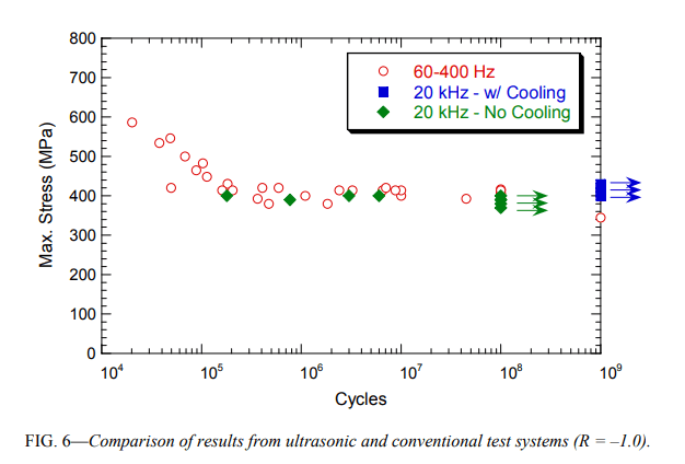
Several researchers have found that conventional (low frequency) S-N tests and ultrasonic S-N tests give comparable results for Ti-6Al-4V. See the image from Morrissey ("Ultrasonic Fatigue Testing of Ti-6Al-4V", Journal of ASTM International, May 2005, Vol. 2, No. 5, Paper ID JAI12024)

Morrissey___Ultrasonic_Fatigue_Testing_of_Ti-6Al-4V___Fig_6_dits8l.png


Morrissey's specimens were unknotched. However, Willertz found the same results for notched Ti-6Al-4V (Kt = 2.4). (Wells, Joseph M.; Buck, Otto; Roth, Lewis D.; Tien, John K. (editors), Ultrasonic Fatigue, The Metallurgical Society of AIME, Warrendale, PA, 1982, ISBN 0–89520–397–9)

rb1957 said:
I'm not sure you should be discarding any stress component at this stage. a cyclic stress when combined with a static stress changes the cycle R, which may be relevant. It's possible (all things are possible until we understand better) that we can't discard the compression part of the cycle.

Static compressive stress does not negatively affect conventional (low frequency) fatigue and I'm not aware of any literature or any theoretical reason that it should negatively affect ultrasonic fatigue. In any case the static compressive stress is very low compared to possible fatigue failure stresses.

rb1957 said:
Has someone mentioned to you that this is a real problem for the industry ?

Having spent my entire career (50 years) in power ultrasonics, I can attest that this is a problem.
 
mfgenggear --

The aluminum horns are made from either extruded material or plate stock. These are generally soft-chrome plated for wear resistance or nickel plated for appearance. Neither plating is designed to improve fatigue performance.

The titanium horns are made from plate stock. Titanium horns may have carbide applied to the face to improve wear.

I know that some platings supposedly increase fatigue life but I haven't seen any good data for aluminum and titanium.

These horns are made in relatively small quantities (compared to automotive) so forging (although interesting) wouldn't be practical.

Generally, CNC is theoretically possible. However, for very deep slots in difficult materials like titanium or D2 steel, the tool will tend to walk due to machining forces; then the desired geometry may not be maintained. To avoid the problem some companies machine with a larger diameter tool (wider slots). However, this can cause performance problems for the horn. Let's save further discussion of machining for a separate thread.
 
Ok, so that s/n data says 300MPa looks to be a good stress to work to. So what do you see with a typical slot ? or an ellipse ?

300MPa is 40ksi ... sounds like a very high stress, although this is Titanium. But you're looking for Aluminium ? Do you have s/n for Al specimens ?

My comment on compression stress is reflecting my ignorance with this specific field. You clearly have plenty of experience to support ignoring the static stress ... fine, NP.

"Having spent my entire career (50 years) in power ultrasonics, I can attest that this is a problem." ... ok, my question was feeling is this a thought exercise or something real. "Surely" there are good design rules for designing these things ? Maybe the industry is living with these things exploding at random times (and you're thinking ... we can do better) ?

I guess you were hoping that someone would run the shape optimisation of the slot for you ? Maybe

You've run an elliptical slot and found an improvement. Great, is it enough ? what does 23% improvement mean.

I think you'll get more milage from cold-working the slot, I'd suggest coining over shot peening. But you'll need testing to quantify the improvement.

A random thought d'heure ... what dictates the width of the slot ? Say you're running with a 1/4" wide slot now. Could you run with a 0.1" (or 0.05") wide slot and have a 1/4 hole at the end (this'd be like my earlier idea of an oversized hole). Again, this hole could be coldworked (see FTI, Fatigue Technology Improvements), then slotted thru ... yes, this would lose much of the benefit of cold working but would retain some benefit (and FTI may have data on this).

another day in paradise, or is paradise one day closer ?
 
yes I am confused here, according to the S/N chart for Titanium is instant failure on titanium is 600 MPa and the safe zone is between 300-350 MPa then material upgrade is the only resort.
that is if the S/N curves for Aluminum is unacceptable results. even if the slot configuration is at it's most best case configuration. S/N curves seems to me is the guide.
 
mfgenggear --

I'm not exactly sure what you're asking/suggesting but maybe the following will help.

Assume that aluminum has acceptable life at 130 MPa ( Assume that the current horn has a maximum stress at the slot of 150 MPa which would be too high. If the slot could be redesigned to reduce its stress by 20% then the new design would have a slot stress of 120 MPa. Hence, problem solved and no need to upgrade to titanium.

On the other hand, if the current horn has a maximum stress at the slot of 200 MPa then a redesigned slot with 20% stress reduction would give 160 MPa (too high). Then, barring other design options, the only recourse would be to upgrade the material to titanium (or another suitable material).
 
dculp

that is exactly my point. if the stress levels exceed S/N curves of aluminum then no configuration changes are going to suffice. or not enough to have a safety factor.
if the material is border line there is no safety factor. in my line of work in aerospace safety factor are very small, so hardware has to be replace or repaired after
so many cycles.
 
I think we should give the OP some credit. I think he understands fatigue life well and knows the difference between mean life and safe life.

His last post shows he has, either in fact or maybe just by way of example, data. If he says "130MPa is good in Al" I don't think we help (I'm one to write that !?) by asking about safe life factors and such.

At the end(?, end? when do these things end?) of this, maybe he should have posted "I want someone to run a shape optimisation of a slot" and given some basic geometry.

One last word, I still think there are other geometries that may work "better" but I don't know enough, and I've run out of ink ...

another day in paradise, or is paradise one day closer ?
 
Status
Not open for further replies.

Part and Inventory Search

Sponsor