chez311 said:
I'm not sure why this particular theoretical boundary could not be discussed in the same context.
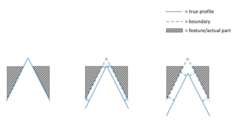
I am not against discussing theoretical boundaries, but I honestly think that "true profile" is not even a boundary. There are inner boundary, outer boundary, maximum material boundary, least material boundary, but not "true profile boundary". This term was used in a questionable way and overused in the context of UAME in both discussions.
True profile is really not part of the UAME definition or its simulation process.
Consider a cylindrical feature of specified diameter 90+/-0.5. What is the true profile? Requoting para. 8.2: "A true profile is a profile defined by
basic radii,
basic angular dimensions,
basic coordinate dimensions,
basic size
dimensions,
undimensioned drawings, formulas, or mathematical data, including design models". Since no basic dimensions or anything of the above involved, "true profile" is irrelevant. If it is still necessary to set a boundary as an origin of "uniform offset" of the UAME simulator (though no such thing is mentioned in the definition) then the most sensible choice for this would be the MMB boundary. Notice how the "Means this" description in fig. 4-31(a) that you brought up mentions progression
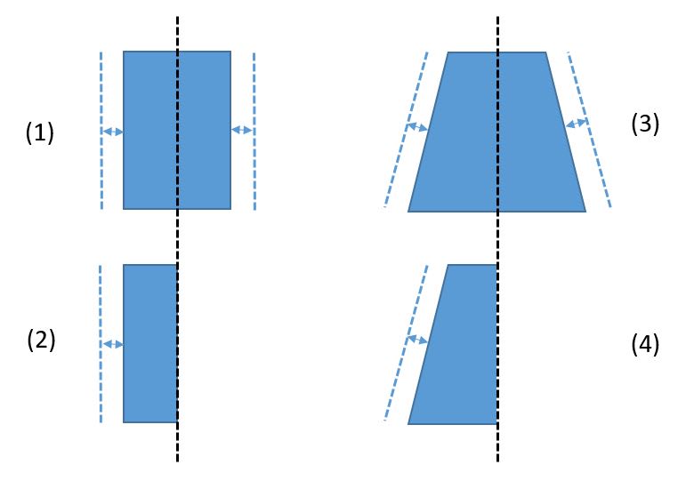
"normal from the MMB", there is no mention of "true profile". Even though this example is in the context of a planar datum feature simulator, this concept can conveniently be translated to the case of a cylindrical feature of size UAME simulation, I suppose no explanation is needed. Obviously, a contraction of an external cylindrical UAME simulator can begin from an envelope larger than the MMB, but whatever happens beyond the MMB envelope, be it uniform offset, non-uniform offset, limited or unlimited, is irrelevant to the process.
On the grounds of this, the MMB boundary can be the "offset origin" for progression of a conical envelope simulator if such origin is necessary. The standard doesn't explicitly define an MMB boundary of a conical shape, but it does lay a solid enough foundation for it; One of the recommended ways to dimension a conical taper is 2.13(c) : "a toleranced diameter at both ends of a taper and a toleranced length. See Fig. 2-19, illustration (a)."
The referenced figure shows a taper dimensioned Dia. 30+/-0.05 at the base and Dia. 20+/-0.05 at the smaller end. Para. 2.13 also defines: "Conical taper is the ratio of the difference in the diameters of two sections (perpendicular to the axis) of a cone to the distance between these sections. Thus, taper = (D - d ) / L. " Naturally, the MMB boundary should have the same "taper" value and cross section of diameter 30.05 adjusted around the base and a cross section of diameter 20.05 adjusted around the smaller end and there is your boundary from which "uniform offset in normal direction" can originate, without dealing with infinite/unlimited offsets.