chez311 said:
I happen to agree with pylfrm that adaptation of the concept of true profile to features of both basic and non-basic definition is useful in instances such as these.
HOWEVER - if we are referring to a conical/tapered profile defined with a basic angle then true profile per the text of the standard would certainly be applicable in this case.
In the thread opened by dtmbiz, I explained further the source of my misunderstanding of the relation of true profile "per the text of the standard" to conical AME simulation, and the related "unlimited offset" issue. It isn't desired that the true profile related discussion drags into that thread so I will repost the relevant part of it here and I would appreciate if you can address this:
Burunduk said:
To be exact, the main argument against tapered features being features of size was the "unlimited offset" from the true profile to the unrelated actual mating envelope simulator during the simulation process, as was shown in
this illustration ... for me, there are still open questions: What does the "true profile" do in that process? This is not a tolerance validation process, but a process intended to derive an axis from a considered feature, i.e. performed prior to tolerance validation that requires anything "true" (true position or true orientation may be more relevant anyway, but then how does the shown offset matter?) And if "true profile" is already there,
why doesn't it follow the feature and/or the envelope simulator? Been looking for clues in the standard to no avail.
I think I now realize that the unlimited offset scenario is based explicitly on the definition suggested by pylfrm: "...uniformly offset from a feature's true profile as far as possible in the direction toward the material." I realize you do not wish to take the standard's definition literally, but even so, we already agreed that the true profile is not some boundary outside or inside the material, it is merely the theoretical exact form of the feature, so where is it relative to the actual feature, to begin with? Without knowing this, there is no basis for talking about normal offset towards the material of the feature and assume it should eventually bring the simulator to contain the feature. When I claimed, based on my understanding of the
non-literal interpretation of true profile you and pylfrm suggested, that true profile has no defined location or orientation relative to the actual feature, your response was a reference to para. 8.2: "Profile tolerances are used to
define a tolerance zone to control form or combinations of size, form, orientation, and location of a feature(s) relative to a true profile." So:
1. Are we dealing with the literal or the non-literal interpretation?
2. If the relationship between the feature and the true profile is based on the true profile being the foundation of tolerance zones to which the feature surface is validated, how does it end up being infinitely offset from the feature under any circumstances?
3. Finally, how is true profile which is a tolerance zones "carrier" for a surface control is even remotely related to UAME - axis derivation?
chez311 said:
The base is truly a separate feature - they intersect at a point/edge yes but that is the limit to their interaction
Yes, but that doesn't make the theoretical envelope that constitutes the unrelated actual mating envelope any less "unrelated", the base doesn't act as a datum feature and doesn't constrain the envelope, not in orientation, and certainly not in location, so I don't see where the problem is.
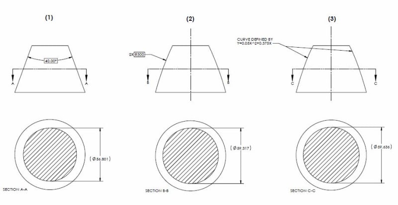
Regarding the 3 figures at the end of your post, I don't see why any of them can't be contained by a potential UAME simulator of the exact inverse theoretical form of the feature,
edit: except for the one reservation I already mentioned several times - the requirement for adjustable size of the datum feature simulator.![[smile]](/data/assets/smilies/smile.gif "[smile] [smile]")