Continue to Site

Eng-Tips is the largest engineering community on the Internet

Intelligent Work Forums for Engineering Professionals

  • Congratulations waross on being selected by the Eng-Tips community for having the most helpful posts in the forums last week. Way to Go!

Can't solve it - retaining wall next to creek in very poor soils

Status
Not open for further replies.

Calif_Eng

Civil/Environmental
Aug 20, 2019
10
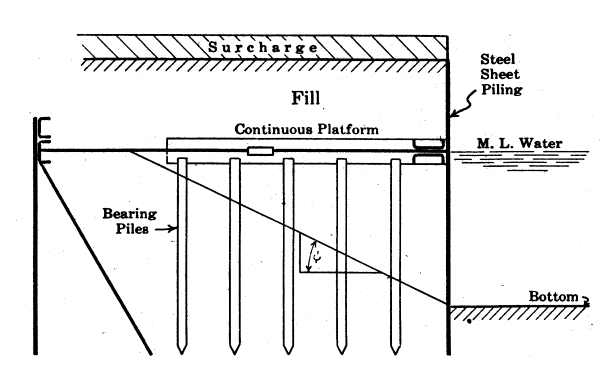
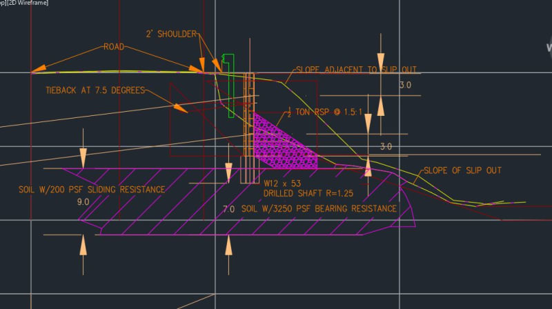
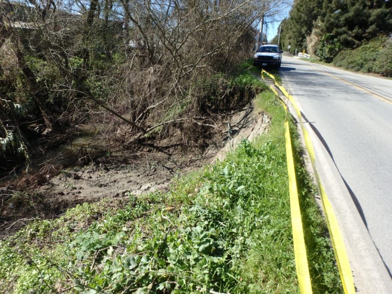
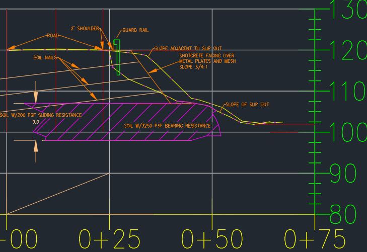
I have an 11 foot wall to support a road next to a creek in an alluvial floodplain in very poor soil. The geotech engineer is not allowing any bearing, only 200 psf in slip friction for nine feet of sandy strata beginning two feet under the lagging for nine feet in depth (13-22ft). Under that its liquefiable until you get down 40 feet. With the LFRD STR I condition I have lateral loads of 1.35EH + 1.75LL + 1.25DC. I was planning a soldier pile single tieback wall, W12x53 r=1.25 @ 8 ft centers, but the vertical resistance factor of the soldier pile for slip friction is .55 which results in 1.25DC exceeding the .55* 200psf slip friction resistance on it's own. The tieback exerts additional downforce on the soldier pile. Alternatives: I can't do RSP as it will get into the creek and environmental review will reject. Intuitively, I'm very leery of a deadman at an angle down to provide additional resistance. About forty feet down the geotech hit some decent material but they only went two feet into it so we'd have to do more geotech. Then I maybe could do piles and and double tiebacks. Any thoughts?
 
Replies continue below

Recommended for you

Will drilling the piles into place help you get enough skin friction? A two foot diameter drill hole has more surface area than an HP12x53.

200 psf seems pretty low for an ultimate/nominal bond strength in what I'm assuming is loose sand. I'd be interested in what the geotechnical engineer was thinking.
 
The piles are drilled (r=1.25), the W section lowered into place, and then concrete.

The radius is 1.25 feet or 2.5 feet diameter.
Circumference = 2* pi * r.
Area = circumference * height
Resistance Force from slip friction = Area * 200 psf * resistance factor of .55 = 2(pi)(1.25'radius)(9' height)(200 psf)(.55 Resistance Factor) =7772 pounds of resistance

Weight of 24 foot steel W12 x 53 with load factor of 1.25 = 1600 pounds
Weight of 13 feet of concrete around embedded steel with load factor of 1.25 = 11700 pounds

Total weight = 13300 pounds
Resistance Force = 7772 pounds No Good

It gets better, but still doesn't work if I go to smaller diameter hole and then lateral forces don't work.

The Geotech thinks it should work, but I don't see how it does with no bearing.

The Geotech says:

Please look more closely at our recommendations for design of the pier supported wall.

The bearing layer for both skin friction and lateral soil passive pressures is a clayey layer that extends from 13 to 22 feet below road surface (paragraphs 23 and 26. The 200 psf ultimate skin friction recommended in our report (paragraph 26 with the correction that this is an ultimate value) is based on that clayey layer having a Su = 500psf.

“Pg 10-132 of the LRFD states the upper 5.0 ft of the shaft is ignored in estimate Rn to account for the effects of seasonal moisture changes.” This does not apply to the clay layer located 13 feet below ground surface so in our opinion you do not need to ignore the upper 5 feet of this layer.

. . .

...it is usually lateral forces that govern the design in these walls.
 
Wondering if lightweight polystyrene fill would at least alleviate some of the loading with the poor soils?
 
Haha, yeah it's usually lateral forces that govern but not always. If it's truly soft material, you don't want the wall sinking and pulling down on tie-back anchors. Sounds like the subsurface conditions/geotech has tied your hands and you have to go deeper, if you want to use solder pile and lagging. Any consideration to soil nails?

I know I'm splitting hairs and it doesn't help you enough but I would say the ultimate skin friction is still a little low based on Su=500 psf. Using the Alpha Method in the FHWA Drilled Shaft Manual, Alpha in this case would be 0.55 and Su is 500 psf therefore fsn = 0.55 x 500psf = 275 psf.
 
I would not think it wise to use soil nails, and maybe not even tiebacks, along a creek, in a flood plane, with "very poor soil." 200 psf friction is only 1.4 psi. Bonding of nails or tieback anchors could be a problem. An 11' high, cantilevered, SSP wall could probably work OK, not be too heavy, and could have sufficient bearing at the better material 40' down. If the soils is really bad, a heavier SSP section or maybe even a combi-wall (H-Z or Pipe-Z wall)could be used.

 
Good point. If water is anticipated above the toe of the wall, then a SNW will most likely not work. If the flood elevation is well below the toe then I would check to see if it’s possible as a SNW would likely cost significantly less than SSP and definitely less than H-Z. Of course the more expensive options would be easier to rest your hat on which is always important.
 
Flood plain may go to top of wall.

Agreed sheet pile wall to below 40' would greatly reduce any future potential scour or meander from the creek. That is likely the most conservative solution.

Thanks for the reference to the FHWA Drilled Shaft Manual. That covers quite a bit of this in more detail. I'm gaining more confidence my methodology is accurate and there's not a big bust I'm missing somewhere.

I wonder if I could socket the soldier pile in the top 2 feet of the 9 foot clay layer, then maybe I can get bearing of 6.5(500) or 3250 psf which for a 1.25 radius shaft gives me 15.9 kips. The weight is greatly reduced since mainly just sitting on clay layer instead of punching through and my vertical forces go to 7.4 kips. The lateral loads will be a bust so I'd have to use another tie back, move the one originally planned at 4 foot depth to 3 feet deep and add another one at 8 foot depth. The Geotech engineer will give me 750 psf for the tiebacks. I think I can get that to work with six inch diameter soil/grout hole gives a bonded length of 36' right at the ROW so yeah that would work. The calcs look like they would pan out for that solution. Super at risk for undermining so probably no go for that unless I protect at least a portion of the 3:1 slope down ten feet to the creek thalweg with some heavy rip rap. I could put wedge of heavy RSP in front of wall at 1.5:1, about 6 feet high nine feet wide 1/2 ton minimum to protect toe of wall. I'll see what the Geotech says about that tomorrow. Service life 75 years. The wall would then just be 5-6 feet above rip rap, much of it buried. That might get by environmental review and avoid a steel sheet pile wall.

They'll probably give it someone else to design if I tell them I want to do a sheet pile wall. The original estimate from field visit post disaster was for a cheap timber lagging soldier pile wall. I've sold them on top down timber backlagging behind the flanges and precast bottom up between the flanges. I've seen that spec'ed for a major subdivision and I prefer concrete for its service life.

What's an H+Z or Pipe-Z wall?
 
Calif Eng said:
...an 11 foot wall to support a road next to a creek...

Maybe a sizable surcharge load on the wall. Perhaps a relieving platform to support vertical loads and reduce lateral wall loading would simply both design and construction.

RelievingPlatform-600_xnwegz.png


[idea]
 
The more I'm learning about the project, the more I'm starting to understand PEinc's recommendation. Are you accounting for a groundwater lag between the front and back of the wall? Is there any concern from the geotechnical engineer that you would be floating the wall above a liquefiable layer? If so, you may need a relatively stiff wall installed down to that dense layer.

HZ Walls and PZ Walls (also known as King Pile Walls) are typically used when a sheetpile wall is not stiff enough. It also helps to cantilever a wall when tie-backs cannot be used or are not good option. The piles come with interlocks for sheets to connect to. Think of it as a Soldier Pile and Lagging Wall but with larger piles and sheets instead of lagging. Its the step between sheetpiles and a straight H wall.
 
I had a recent project where the project geotech designed a drilled-in soldier beam and precast concrete lagging retaining wall along the tidal Schuylkill River. The site had similar poor soil conditions (soft river silt). Rock was relatively high and the geotech required socketing the soldier beams or king piles into bedrock. It would have been very expensive and would have required a temporary cofferdam. We proposed and designed a cantilevered, drilled-in H-Z SSP wall (sheets were driven to refusal between the drilled-in, rock socketed, king piles) that was then built by my client. The wall supports a center city, riverside walking trail with a freight rail line next to the trail. All work was done from land, without need of a cofferdam or dewatering. The non-profit, trail agency was very happy.

Original Wall Design
Original_Wall_Section_g0i8o9.jpg


Alternate Wall Design
PDCA_Photo_urtdcp.jpg


Definitely appreciate all the help. Those 2'-6" caissons would definitely work. I assume the concrete simply displaces the water in the caisson, hence no dewatering. I have water at 15 ft down. If I do go down 40 feet to good material are there any considerations with buckling from slenderness if the middle is liquefiable?

Drawing attached of previous idea of double tieback wall with 2 ft embedment in top of 9 ft clay layer. RSP to protect toe. Geotech hasn't given me any bearing, but I think she was presuming punched through. FHWA Drilling Manual would give 3250. Checking with her today.

Seems like there's an elegant solution somewhere where lateral forces are taken by tiebacks and vertical bears on the clay layer. The soldier pile will keep the road open. If I went to a traditional retaining wall on top of the clay, the road would have to be closed. Its almost like I want to be able to put the soldier pile tieback wall in (to avoid a big OSHA cut that requires the whole road) and then get under it and put in a concrete grade beam attached to the soldier pile on top of the clay layer for bearing.


Capture_sdt9pu.jpg


Here's a picture of the site
P2280086_wdj8fk.jpg

 
What's the reason for the wall? Did the slope fail? Kind of looks like a slope repair job where you would re-establish the slope and reinforce it with soil nails, if necessary.

If you need the wall then I'm torn between floating the wall with tie-backs with the realization that liquefaction could cause differential settlement and result in additional stresses on your tie-backs or just installing a cantilever wall down to the dense material. If you did install the piles down to the dense material, you would want account for pile downdrag loads from liquefaction settlement.
 
The wall is to move the improvements away from the creek. This has to go through NEPA/CEQA/US Fish & Wildlife review and they don't want anything near the creek. I hear you on the soil nails, I was just looking into. I could slope at 3/4:1 per OSHA max and then use soil nails. Do soil nails require a facing? I see mesh in some examples and the environmentalists will reject that as they say critter will get caught in there and die. They do not allow gabion baskets in the riparian area next to a creek. It would have to be a shotcrete facing. Perhaps:
SOIL_NAILS_rr9yun.jpg


We've never done a soil nail wall design in house, but that may be the best. Presumably you'd have to take half the road to ramp down to build it but that would be okay.
 
If it was my job, I'd be pushing for the sheet pile wall, with tiebacks if it reduced the required section modulus of the sheet piling enough to be worthwhile (I'd be surprised if it did), although I wouldn't assume the necessity of going the 40' to bedrock, except as an upper limit for estimating purposes.

Don't forget to include the lateral force due to an impact on the guardrail, assuming guardrail is going to be installed (seems likely given the proximity to the creek).
 
If there is decent soil somewhere above the rock, the sheet piling probably would not need to go to rock unless the design showed it is needed.
If the soil liquefies, why worry about the wall? The road will probably fail; and then, what would the wall be supporting?
How many linear feet of wall will ne needed? Why can't you just fill in the failed area with rip rap and forget about the wall? After all, the rest of the road has no wall.

 
Agreed, I could do RSP at 1:1, but managing engineer won't consider it at 1:1 and 1.5:1 will take it to the thalweg so environmental review likely to reject.

Talked to the Geotech. She won't give me any bearing on clay layer so floating soldier pile wall on clay layer with two tiebacks out. That felt risky anyway. She's not okay with soil nails either but okay with helical anchors so that is the most likely option at this point. She likes steel sheet pile (SSP) as well as best option. Unfortunately, SSP is likely to be rejected as funding was for soldier pile wall and my agency has never done SSP in our county that we're aware of. If environmental review rejects helical anchors w/shotcrete to stabilize 3/4:1 fill embankment, then we might be forced to SSP. Geotech says this is one of the worst cases encountered but other engineers having trouble with the vertical using LFRD doing some contract work for us as well. I got a contact so going to check in with them.

Factor of Safety for this specific case of axial compression on drilled shaft in clay being resisted by slip friction only is 2.87. How does this compare to ASD? Does anyone know? I haven't used ASD since I graduated in 1991.

I'll probably cost out helical anchors vs. SSP, but presumably SSP way more, obviously much better as well. Thanks all for your help. Much appreciated. I mainly do development review and subdivision map processing; I find this much more fun. Thanks again.
 
Cost-wise, the SSP is typically less expensive than a soldier pile wall, especially if the piles have to be predrilled and grouted, which you seemed to indicate was the type you planned on using. The design is also simpler. We only use soldier piles for that type of application if we can't get adequate embedment depth for sheet piling.

I think the helical anchors require specialized equipment, so the mobilization cost will likely make that option expensive for such a small job. In most areas, it'll be the same for predrilling the holes for the soldier piles (or driving the H piles, for that matter).
 
Calif_Eng, instead of RSP, maybe the managing engineer would consider gabion baskets, stepped back to equal a 1:1 slope.

road....XX
............ XX
...............XX
.................XX......... creek

 
Status
Not open for further replies.

Part and Inventory Search

Sponsor