Tek-Tips is the largest IT community on the Internet today!

Members share and learn making Tek-Tips Forums the best source of peer-reviewed technical information on the Internet!

  • Congratulations TugboatEng on being selected by the Eng-Tips community for having the most helpful posts in the forums last week. Way to Go!

Beam Reinforcement Calculation 2

Nick6781

Structural
Joined
May 15, 2024
Messages
55
Location
CA
Let's say I need to use a web plate instead of a flange cover plate (I know...) to reinforce a beam. How do I calculate the required weld to ensure the section acts compositely? The shear flow equation gives the shear along a horizontal plane, but in this case, the faying surface is vertical. I can't quite wrap my head around it.


1751068113227.png
 

Attachments

  • 1751068099044.png
    1751068099044.png
    12.3 KB · Views: 5
Thanks HTURKAK, I see it now. Very neat!

Once again, I apologize to everyone for prolonging this discussion to so many posts. I will try to keep quiet on this subject from here on.
 
Last edited:
👋 BAretired

No need to apologise, now I'll take the blame for continuing the discussion. ;)

It is nuanced because the VQ/I is an inherently correct formula from theoretical fundamentals. Though how it understood and applied is more nuanced than people can realise. For example, from a calculative perspective there is nothing in the calculation telling WHERE the shear needs to be transferred and there is nothing even to require that the elements be contiguous (connected or each other).

Furthermore there is NOTHING in that formula that involves "picking a point". So this notion of only calculating shear flow at a point and especially only calculating Q in one direction (eg upward or downwards) is fundamentally flawed no matter what a textbook says. (Though typically the boundary between two areas becomes the point or plane where one is choosing to consider the shear flow.)

EG;

1751675011543.png
This section on the left still has a calculable V, Q & I. You can calculate the shear flow required between A & B but all that tells you is that VQ/I shear must be flowing between A and B, even though there is no obvious way it can nor an obvious way for V to be identical and thus one might rightly question that it is a indeed a single section. So we can fix that.


1751675426365.png
Now we are looking at something a little more familiar. We can calculate V,Q,I and work at the shear demand at any point. we want. That break between section A and B can be anywhere we choose. Also we can work out Q on whichever area we choose. The normal way of calculating the above would be to calculate the Q of section B. But you can just as easily calculate the Q of section A and get the same answer. If we choose to calculate the Q for section A we get a value of ZERO for the web of A and the value of Q of section A flange is equal to the B flange. So that all checks out, something would be amiss if the VQ/I gave different results if you choose the opposite section.


1751676428809.png
Likewise we can go nuts calculating the shear flow in this double-I section however you want. But if you choose to calculate Q of (A&B) or (A' & B') then you will get Q=0. You can call it a compound section as much as you want. You can weld those flanges together if you choose. However as long as you can ensure that V is equal then the VQ/I=0 and there is no shear flow. The original example is no different. There is no shear flow between the plates and the beam because Q =0


1751677279704.png
I hope this example above will convince you against the perverse notion of picking a point and only calculating Q above or below it. If I was going to size the welds for section C I'd consider ALL of the area of C to calculate Q, not just the bit 'above' my weld.


Oh, and there is one more method of analysis that I found really useful graphically and match up to calculated results within a 5%.
I modelled two beams
-200mm deep, 100mm wide flange, 10mm thick web and flange, point loaded with 100kN, 2m long
The top beam exactly matches hand calcs as the section is drawn perfectly. The lower one is slightly out because it is actually made of a grillage of members (20x10mm).

1751677940495.png

Because this is a grillage you can readily see the shear flow in discrete elements. A grillage of 1D elements is a poor man's 2D or 3D FEA. But it is often more interpretable and user friendly than FEA.

1751678247785.png
You can measure and visually see the shear flow and also the shear lag around the supports. My measured value is 5.63kN of shear per 20mm, the hand calculated value is 5.91kN. So 5% out, but it isn't a perfect model but it is good to play around with and observe the shear flow. I also found it quite satisfying to see the shear flow at the top add up in 20mm segments to equal the total axial load in the flanges at centre. Again something you should expect but satisfying to see it incrementally and visually.

I also modelled the example of the I beam with plates. The result is as expected, no shear flow as there is no stress/strain differential between the plates and the web. If people are interested I can post more. But I think this post has been long enough.
 
Last edited:
👋 BAretired

No need to apologise, now I'll take the blame for continuing the discussion. ;)

It is nuanced because the VQ/I is an inherently correct formula from theoretical fundamentals. Though how it understood and applied is more nuanced than people can realise. For example, from a calculative perspective there is nothing in the calculation telling WHERE the shear needs to be transferred and there is nothing even to require that the elements be contiguous (connected or each other).

Furthermore there is NOTHING in that formula that involves "picking a point". So this notion of only calculating shear flow at a point and especially only calculating Q in one direction (eg upward or downwards) is fundamentally flawed no matter what a textbook says. (Though typically the boundary between two areas becomes the point or plane where one is choosing to consider the shear flow.)

EG;

View attachment 14869
This section on the left still has a calculable V, Q & I. You can calculate the shear flow required between A & B but all that tells you is that VQ/I shear must be flowing between A and B, even though there is no obvious way it can nor an obvious way for V to be identical and thus one might rightly question that it is a indeed a single section. So we can fix that.


View attachment 14871
Now we are looking at something a little more familiar. We can calculate V,Q,I and work at the shear demand at any point. we want. That break between section A and B can be anywhere we choose. Also we can work out Q on whichever area we choose. The normal way of calculating the above would be to calculate the Q of section B. But you can just as easily calculate the Q of section A and get the same answer. If we choose to calculate the Q for section A we get a value of ZERO for the web of A and the value of Q of section A flange is equal to the B flange. So that all checks out, something would be amiss if the VQ/I gave different results if you choose the opposite section.


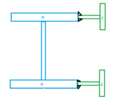
View attachment 14872
Likewise we can go nuts calculating the shear flow in this double-I section however you want. But if you choose to calculate Q of (A&B) or (A' & B') then you will get Q=0. You can call it a compound section as much as you want. You can weld those flanges together if you choose. However as long as you can ensure that V is equal then the VQ/I=0 and there is no shear flow. The original example is no different. There is no shear flow between the plates and the beam because Q =0


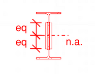
View attachment 14873
I hope this example above will convince you against the perverse notion of picking a point and only calculating Q above or below it. If I was going to size the welds for section C I'd consider ALL of the area of C to calculate Q, not just the bit 'above' my weld.


Oh, and there is one more method of analysis that I found really useful graphically and match up to calculated results within a 5%.
I modelled two beams
-200mm deep, 100mm wide flange, 10mm thick web and flange, point loaded with 100kN, 2m long
The top beam exactly matches hand calcs as the section is drawn perfectly. The lower one is slightly out because it is actually made of a grillage of members (20x10mm).

View attachment 14874

Because this is a grillage you can readily see the shear flow in discrete elements. A grillage of 1D elements is a poor man's 2D or 3D FEA. But it is often more interpretable and user friendly than FEA.

View attachment 14875
You can measure and visually see the shear flow and also the shear lag around the supports. My measured value is 5.63kN of shear per 20mm, the hand calculated value is 5.91kN. So 5% out, but it isn't a perfect model but it is good to play around with and observe the shear flow. I also found it quite satisfying to see the shear flow at the top add up in 20mm segments to equal the total axial load in the flanges at centre. Again something you should expect but satisfying to see it incrementally and visually.

I also modelled the example of the I beam with plates. The result is as expected, no shear flow as there is no stress/strain differential between the plates and the web. If people are interested I can post more. But I think this post has been long enough.
Great post. The only thing left for you to do here is to grab a W-shape, a few plates, and start building a model for us :LOL:
 
Thanks. The one thing I did leave out is referring to NET or TOTAL shear. I would think by now this would be clear, but I've made the mistake many times of thinking things were clear when they are not.

If you break up section C from section A below and calculate QV/I=0 then you would be correct but it wouldn't do you much good if you were trying to size up welds between C & A. Correct in that the NET/TOTAL shear between section C and A is zero, but incorrect because you do have shear equal and opposite shear at the boundaries between A&C.

Again in the situation of the plates you don't have this issue because the plates are a continue piece so the shear nets out. As long as deflection is the same then the stress/strain gradient between the web and the plates is zero so even if you weld/glue/bolt there is no longitudinal shear flow.
1751684376977.png
 
My understanding for the weld calculation below is to find the Q value for the upper or lower green shape.
The upper fillet welds must resist a shear flow of VQ/I where Q is taken for the upper green outline.
Similarly, the lower welds resist VQ/I where Q is for the lower green outline.
 

Attachments

  • 1751750104125.png
    1751750104125.png
    15.2 KB · Views: 7
Last edited:
I don’t believe shear flow is 0 at the C/A interface it’s my understanding that you can look at the vertical shear plane at C/A and use the Q as the first moment of area for the C area about the composite centroid sim to the below pulled from Mechanics of Materials 7th edition by Beer:

IMG_2816.jpeg
 
My understanding for the weld calculation below is to find the Q value for the upper or lower green shape.
The upper fillet welds must resist a shear flow of VQ/I where Q is taken for the upper green outline.
Similarly, the lower welds resist VQ/I where Q is for the lower green outline.
Agreed 100%.

Sorry, I thought the point being made was fairly clear that calculating the total area C wouldn't be useful. You would need to calculate the Q area separately as you both point out.

Calculating them both together gives you the NET shear flow of the top and bottom segments which is pretty unhelpful in this example.


I don’t believe shear flow is 0 at the C/A interface
It is 0 when you add the value of the TWO C/A interfaces. They are equal in magnitude but opposite in sign. Adding them or calculating the NET shear flow into C is pretty unhelpful but it is NOT an invalid calculation. I'm have just been bring up examples like this to emphasise the SIGNED nature of Q.
 
Last edited:
Agreed 100%.
Great!
Sorry, I thought the point being made was fairly clear that calculating the total area C wouldn't be useful. You would need to calculate the Q area separately as you both point out.

Calculating them both together gives you the NET shear flow of the top and bottom segments which is pretty unhelpful in this
We have total agreement. Thanks human909.
 
I'm back. Good discussions so far.


In the flange, the direction of the shear flow lies in a horizontal plane. I'm supporting human909's argument with the diagram below:
So this notion of only calculating shear flow at a point and especially only calculating Q in one direction (eg upward or downwards) is fundamentally flawed no matter what a textbook says. (Though typically the boundary between two areas becomes the point or plane where one is choosing to consider the shear flow.)

1751925612264.png

Regarding the textbook explanations:


1751925667025.png
In my beam, the horizontal stress induced by the differential moment in the plates above and below the neutral axis cancels out, as I mentioned earlier. Therefore, there is no horizontal shear flow between the plates and the beam.
In addition, analyzing a cube from the plate should yield the same conclusion, there shouldn't be shear flow on the front and back surfaces of the cube.

In summary, I agree with human909's point—only vertical shear transfer needs to be considered, so welds are required for vertical shear only.
 
Nick6781 said:

Only vertical shear transfer needs to be considered, so welds are required for vertical shear only.


That is simply not true. Your own diagrams show otherwise.
 
Has Koot gotten into this one yet? I haven't read the four pages yet.

No, I've been waiting for him to show up. Maybe he is busy, or bored with the topic. He did provide input in the previous thread linked largely along similar lines of argument as what I have put forward.
 
It seems like there might be some confusion here on shear flow within an element vs shear flow transferred between elements. This is an important distinction.

See my previous post regarding shear flow transferring between the beam and side plates. I maintain that the Q term for the side plates shear flow transfer is 0 since the neutral axis of the plates corresponds to the W beam; therefore the shear flow transfer is 0 at the weld locations shown.
 
I don’t believe shear flow is 0 at the C/A interface it’s my understanding that you can look at the vertical shear plane at C/A and use the Q as the first moment of area for the C area about the composite centroid sim to the below pulled from Mechanics of Materials 7th edition by Beer:
Blast from the past. I used the 1979 version of this in College. Probably 1st edition back then!
 
It seems like there might be some confusion here on shear flow within an element vs shear flow transferred between elements. This is an important distinction.
I agree that there is confusion.
See my previous post regarding shear flow transferring between the beam and side plates. I maintain that the Q term for the side plates shear flow transfer is 0 since the neutral axis of the plates corresponds to the W beam; therefore the shear flow transfer is 0 at the weld locations shown.
I don't believe shear flow is zero between I-beam and the top or bottom half of each side plate, and I believe that a weld is required top and bottom of each side plate in order to consider the section composite. Otherwise, the side plates and I beam are not acting compositely. I do agree however, that the side plates add very little to the strength of the composite beam, even when adequately welded.
 
I don’t believe shear flow is 0 at the C/A interface it’s my understanding that you can look at the vertical shear plane at C/A and use the Q as the first moment of area for the C area about the composite centroid sim to the below pulled from Mechanics of Materials 7th edition by Beer:
Exactly Celt83, and similarly you can look at the vertical shear plane between the upper and lower halves of the side plates in the original post. Q is the first moment of area for the upper or lower half plate area about the centroid of the combined section. Each weld must be designed to resist VQ/I.
 
Sorry if repeating. didn't read all replies. Free body diagrams are good checks to shear flow calculations and probably give more intuitive results just in different forms. Away from ends FBD will show zero net horiz force, vertical force equal to share of shear variation, and restraint to plate rotation. Last one will be zero over full length so judgement whether to deal with welds. Near ends you transfer plate shear back to beam and, develop bending moment over length equal to plate depth.
 
Me: "develop bending moment over length equal to plate depth."

Never mind that bit. I think it doesn't happen when plate are at neutral axis level. Does happen if you strengthen near flanges.
 
Let's say I need to use a web plate instead of a flange cover plate (I know...) to reinforce a beam. How do I calculate the required weld to ensure the section acts compositely? The shear flow equation gives the shear along a horizontal plane, but in this case, the faying surface is vertical. I can't quite wrap my head around it.


View attachment 14586


you’re right, the usual shear flow equation q=VQ/Iq = VQ/Iq=VQ/I gives you the horizontal shear flow between flanges and webs, but when you’re using a web plate to reinforce a beam, you’re really relying on the welds to transfer force between the existing section and the plate so they act together.

In this case, you should treat it like designing a built-up section. The goal is to size the welds so they can resist the longitudinal shear flow needed for composite action. Even though the faying surface is vertical, the shear is still longitudinal — parallel to the beam axis — because you’re trying to prevent slip between the plate and the beam.


A practical approach is:
  1. Calculate the longitudinal shear flow at the interface using q=VQ/Iq = VQ/Iq=VQ/I.
  2. Use that shear flow to determine the required weld size.
    • For fillet welds, use F=0.707×tw×fwF = 0.707 \times t_w \times f_{w}F=0.707×tw×fw per unit length, where twt_wtw is the weld leg size and fwf_{w}fw is the weld strength.
  3. Check that the total weld capacity per unit length meets or exceeds the required shear flow.

Also, make sure the welds are spaced continuously enough to avoid stress concentrations and local buckling. A continuous fillet weld is usually best for this type of retrofit.

If you’d like, share your beam details (loads, span, plate size) and I can help you run through an example!
 
There really shouldn't be any debate.

I don't believe shear flow is zero between I-beam and the top or bottom half of each side plate,
Try calculating the strain between the plate and the I-beam web. Compare the two. See what results you get. If the strain is equal then how is force transferred?

I believe that a weld is required top and bottom of each side plate in order to consider the section composite. Otherwise, the side plates and I beam are not acting compositely. I do agree however, that the side plates add very little to the strength of the composite beam, even when adequately welded.
The side plates and I beam aren't act compositely. That is the case whether you weld the top an bottom or not. Calculate the I/Z/S values and see what you get. They are all identical whether they are composite or 'sistered' in vertical shear only. That is what the rational logic chain implies and that is what the calculation show. **

**Shear lag and any non continuous vertical shear connection will inevitably induce some shear flow but it is pretty negligible and pedantic if we really want to highlight this. For what it is worth these effects were evident in my structural analysis model presented earlier but they were about three orders of magnitude below the shear flow. AKA negligible.
 

Part and Inventory Search

Sponsor

Back
Top