Continue to Site

Eng-Tips is the largest engineering community on the Internet

Intelligent Work Forums for Engineering Professionals

  • Congratulations KootK on being selected by the Eng-Tips community for having the most helpful posts in the forums last week. Way to Go!

Aluminum Weldment Design Help 4

Status
Not open for further replies.

Andre3

Mechanical
Mar 2, 2019
53
I have recently moved from a mechanical design role into engineering at my small R&D company figured I would try reaching out to you folks for some help and direction as I do not have other colleges to consult with. I am looking to design a weldment between two 6061-T6 components supporting a very strong solenoid magnet. This had been a bolted connection but the bolts failed after the system was overloaded and now we would like to weld them together for a stronger, permanent connection. My thought was to chamfer the parts to make for a groove weld to hold them together but I am mostly unfamiliar with weldment design.

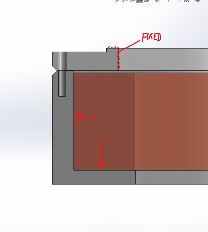
From what I have seen it looks like to be conservative I can expect the welded area to behave like 6061-O which is dramatically weaker. There is an axial magnetic force of about 250 kN downward and an outward radial force that is still being evaluated, for now I am treating it as 0.5 MPa acting on the inside wall of the support. Where should I start with evaluating the stress experienced at the weld and how it will behave? I have attached some snips of a simplified model for discussion.
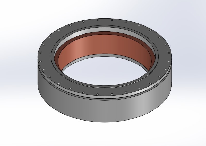
coil_and_bobbin_t3fzkh.jpg

cross_seciton_snip_mtc94x.jpg
 
Replies continue below

Recommended for you

mfgenggear

There is no cryogen and the coils do not heat up significantly, the source of the axial (dominant) and radial forces are from the magnetism. I don't think it is a differential thermal contraction problem with the aluminum structure and the coil. My thought was that the bolt failure caused a quench (when the coil goes resistive and you get massive heating) and I haven't thought of it much the other way around. We have quench protection that automatically starts dumping the current out the magnet if a resistance is measured so I think it is unlikely but I will think more about that.
 
Hi Andre3

Thanks for the update, yes I can see that the stainless is more ductile than the inconel 718 but when I googled I found that inconel 718 was good at -423F see link attached courtesy of 3DDave
Yes I can see the formula's you say you used but I meant see your workings because the formula only apply's if the two materials are in contact and in my opinion at the cooled temperature there is no connection.

Another question are the magnets operational during cooling or are the only turned on after cool temperature is reached?

If I take the residual stretch left in the bolt after cooling that you quote as 0.0001 then I get a residual preload of 19.3N, now that is an over estimate because I used the bolt O.D. and not the root diameter.


“Do not worry about your problems with mathematics, I assure you mine are far greater.” Albert Einstein
 
Andre3,
What is the critical temperature of the coil material, and does your power source have provision to quench the energy dump that takes place should excessive temperature rise occur?
 
Andre3, as to shape, yes.

Similar to a tool I designed to generate 30,000 lbs of force resisted by the screws in the bolt circle.
20201230_131925_lb2ri7.jpg


Ted
 
"My thought was that the bolt failure caused a quench (when the coil goes resistive and you get massive heating) and I haven't thought of it much the other way around. We have quench protection ..."

Andre3, if the quench circuit is inadequate you have an explosive release that will result in failure of the coiler enclosure,

Good Luck,
 
desertfox
I am confused on what you are looking for, I used those formulas to draw my conclusion and showed my work (other than the arithmetic) in the first set of notes. Unless I am misunderstanding something, it seems like formula shown in the thermal stress section would be how you determine if the joint stays in contact after cooldown. If F ≤ 0 then there is no contact F ≥ 0 then there is still load on the bolt. Am I missing something?
The magnets are not turned on until the base temperature has been reached, this takes many hours.

hacksaw
The critical temperature is field dependent and varies over the cross section of the coil. We have done well using voltage drop as detection method but our electrical engineer has written all the code and I am new to it all so I cant speak on it very much. We have talked about adding temperature triggers but thermally our systems have performed very well and we haven't needed it. Quickly dumping the current out of the coils should be avoided so if we see any temperature rise we tend to slow the ramp rate and let the cooling catch up.
 
desertfox

.0001/30 = 3.33e-6
F = EAe = 2.37e11*20.1e-6*3.33e-6 = 15.87 N
right?
 
Hi Andre3

I think the bolt and Aluminium alloy are not in contact when the thing is cooled down, your conclusion is that they are so what I was requesting was your workings out so I could see how you arrived at that conclusion, you have better information than I but what I am also saying is that if you are correct and there is tension still in the bolt ie you say 3.4kN then maybe if we increase the bolt load on assembly at room temperature you might be okay with the design.
I am also confused by your last post where you state there is 0.0001mm stretch still in the bolt because that only equates to 19N preload and not 3.4KN.

yes I agree with your last post.

“Do not worry about your problems with mathematics, I assure you mine are far greater.” Albert Einstein
 
Hi Andre3

The bolt notes that show joint stiffness etc don't have anything to do with the temperature, the calculations are say correct at whatever temperature they are assembled at but any heating and cooling of the joint must have the new temperature stresses added to them, so for example in the link exp 2.4 that only works because the brass or copper tube expands more than the steel, if you consider that instead of heating the rod and tube you cooled it down then the tube would freely contract and there would be no temperature stress and the rod/bolt would loose its tension and this is what I am saying is happening in your case. If the bolt were made from aluminium alloy and the housing from inconel 718 you could use those formula.

“Do not worry about your problems with mathematics, I assure you mine are far greater.” Albert Einstein
 
desertfox

Not trying to ask a dumb question here.
Your the expert here, but how does the preload contribute to the bolts failing.
what puzzles me this
for example the yield stress of the aluminum is significant less than Inconel.
yet the bolts failed and not the cap. is this due to the Concentrated force (moment) on the bolts? and because the moment is
more spread evenly on the cap?

as an example bolts on an automotive engine head secured by bolts to the head, and preload on these bolts are important.
to maintain a seal by means of a head gasket. torque values(preload) will require retightening to maintain the exact preload.
due to thermal cycling of the engine, and expanding and contracting, also the temperature the bolts cycle thru.
but it is very rare if not at all these bolts will have catastrophic failure. not sure if this is a good example because
the aluminum heads and bolts are very robust. and with a large safety factors.

I am Intrigued that the original engineer calculated acceptable values. yet there was a missed stress value if that is the correct description.
again a failure analysis of the bolts is required by a metlap, to verify the bolts do not have a material defect, was it the result of hydrogen embrittlement.
or mis-heat treated parts. or was there a defect in the original parent material.
a formal electron microscope analysis , and a spectral analysis, and a verified the parts were heat treated to the correct hardness.
if the bolts pass with no defects, then a failure analysis of why the bolts failed.
the key is analyze if in fact the bolts were over loaded exceeding the yield stress values.
is there a hiccup of coils as noted above.

 
desertfox

I took some more notes that I hope clears things up. It is mostly the same information as my last set of notes but a bit more broken down. I used one website to get the stiffness formulas (the joint stiffness is roughly constant with temperature, less than 10% higher at 3K vs 293K) and the other to calculate the thermal loading.
[URL unfurl="true"]https://res.cloudinary.com/engineering-com/image/upload/v1609369175/tips/Bolted_Joint_Thermal_Effects_c8pmcb.pdf[/url]

"I am also confused by your last post where you state there is 0.0001mm stretch still in the bolt because that only equates to 19N preload and not 3.4KN."
That was my attempt at showing that I don't understand how you came to the conclusion that the joint is not connected when cold by using your method to find the remaining bolt strain. Using your method I came up with 16N bolt tension and with the method I outlined I came up with 3.2kN
 
Hi mfgenggear

What we believe as happened is this:- the whole thing was assembled at room temperature magnet,aluminium housing etc with the Inconel718 bolts; however there was no tightening control on the bolts so each bolt would have had a different preload of unknown magnitude but that isn't the big issue but does contribute to the failure.The whole assembly is placed in a sealed chamber which is then subject to vacuum and the whole thing cooled to around -275 degrees centigrade, unfortunately during this cooling the Aluminium Alloy has a higher coefficient of contraction than that of the Inconel bolts and we believe that all the bolt preload was lost or most of it due to the aluminium alloy being able to contract more and loose contact with the bolt, effectively making the joint loose. There are two sealed chambers both with assembled magnets and positioned opposing each other some distance apart, when the both magnets are switched on they act to attract each other with a force around 250kN and because the bolt preload was lost both magnets move toward each pushing on the aluminium covers and transferring the external load directly to the bolts and subsequent failure, now not all the bolts failed and those that didn't fail had the helicoil insert pull out of the housing, in preference to the bolt failing, the OP indicated that too short an helicoil was used or the helicoil was poorly installed.

I'm no expert by the way but this is my understanding thus far[bigsmile]

“Do not worry about your problems with mathematics, I assure you mine are far greater.” Albert Einstein
 
Hi Andre3

Thanks for your last post, I think I understand what you were doing now in the first set of notes you posted but it wasn't clear to me then, I will look at what you have just posted and get back to you[bigsmile]

“Do not worry about your problems with mathematics, I assure you mine are far greater.” Albert Einstein
 
Thanks for the reply Desert Fox, true Gentlemen. and you are an expert my friend.
I looked at the force applied and was also puzzled by that.
the force is applied on the opposite faces of the caps. unless it has a mechanism
that holds the assembly in place with the cap. the magnets are attracted as shown in the OP first post.
thus 250Kn force which exceeds stress values of the bolts.
unless I am still confused. :)
 
Hi mfgenggear
I should of added that if the load was distributed evenly across all the bolts then the bolts should have held; however in practice loads are never spread that evenly and so whats happened is a few bolts have been overloaded and failed and then there are less bolts to take the full load, so the bolts fail progressively or the helicoils pull out[bigsmile]

“Do not worry about your problems with mathematics, I assure you mine are far greater.” Albert Einstein
 
From the previous messages it seems that the load is dynamic and the fix is some combination of more bolts, longer engagement, larger bolts, longer helicoils, better control of the pre-tension.

I'd be amazed if the attraction was truly 100% uniform - could that have a contribution?

Has welding been completely ruled out?
 
"Quickly dumping the current out of the coils should be avoided so if we see any temperature rise we tend to slow the ramp rate and let the cooling catch up."

That's right, but loss of incoming power can also trigger the energy release, is your power source designed to trigger shunting the coil discharge to avoid mechanical failure?
 
IFRs
I think of the loads as quasi-static, if there are any rapid changes something is going wrong. I agree I think the solution will involve all of those characteristics.

The design is for everything to be very symmetrical but it cant be perfect. Especially with loose bolts that had uneven preloads to begin with, I think that contributed.

I am leaning away from welding now that it is clear the bolted joint was not properly designed and I am understanding how to fix it. I am still open to welding if anyone has a different opinion.

hacksaw
On a high level, the charging circuit and quench protection we use are handled by a 45+ year veteran physicist specializing in SC coils and a really good EE so I trust they have it all very well sorted out. To try answering your question, it is my understanding that we control our charging circuit and quench protection with custom in house software and it has been designed and tested to prevent excessive mechanical stress and heating from eddy currents.
 

Andre3,
I am sure your system works as intended, but how can it fail?

The various failure possibilities need a thorough review as well. That takes time and open to addressing challenging possibilities.
 
Hi Andre3

I agree with your calculations, I saw where I was going wrong I was just thinking that the free contraction of the aluminium was greater than that of the Inconel718 so sorry for the confusion, I calculated a different way and got a residual preload of about 2.967kN about 13% difference to your answer.
So either way there is still bolt preload present but not that it will do any good.
Now I calculated that you can preload the bolts to around 11kN at room temperature before the screw head embeds itself into the aluminium alloy but you would need to be much higher than that to get the lid to hold at the cooling temperature and the only way to do that is increase the number of bolts if you want to stay with the M6.


“Do not worry about your problems with mathematics, I assure you mine are far greater.” Albert Einstein
 
Status
Not open for further replies.

Part and Inventory Search

Sponsor