Continue to Site

Eng-Tips is the largest engineering community on the Internet

Intelligent Work Forums for Engineering Professionals

  • Congratulations waross on being selected by the Eng-Tips community for having the most helpful posts in the forums last week. Way to Go!

Aluminum Weldment Design Help 4

Status
Not open for further replies.

Andre3

Mechanical
Mar 2, 2019
53
I have recently moved from a mechanical design role into engineering at my small R&D company figured I would try reaching out to you folks for some help and direction as I do not have other colleges to consult with. I am looking to design a weldment between two 6061-T6 components supporting a very strong solenoid magnet. This had been a bolted connection but the bolts failed after the system was overloaded and now we would like to weld them together for a stronger, permanent connection. My thought was to chamfer the parts to make for a groove weld to hold them together but I am mostly unfamiliar with weldment design.

From what I have seen it looks like to be conservative I can expect the welded area to behave like 6061-O which is dramatically weaker. There is an axial magnetic force of about 250 kN downward and an outward radial force that is still being evaluated, for now I am treating it as 0.5 MPa acting on the inside wall of the support. Where should I start with evaluating the stress experienced at the weld and how it will behave? I have attached some snips of a simplified model for discussion.
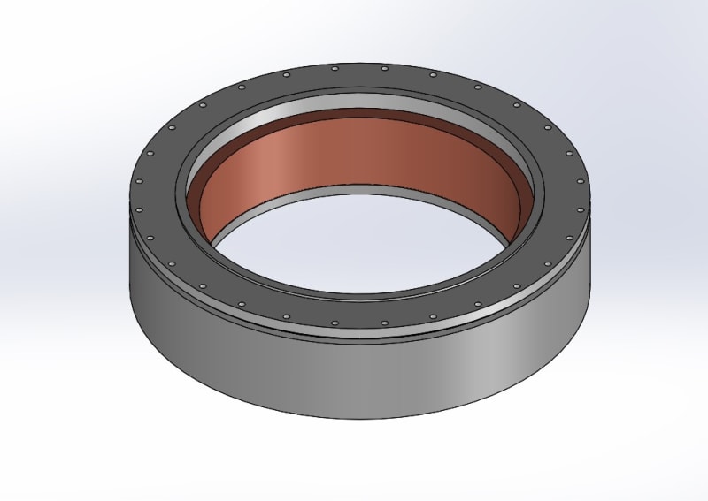
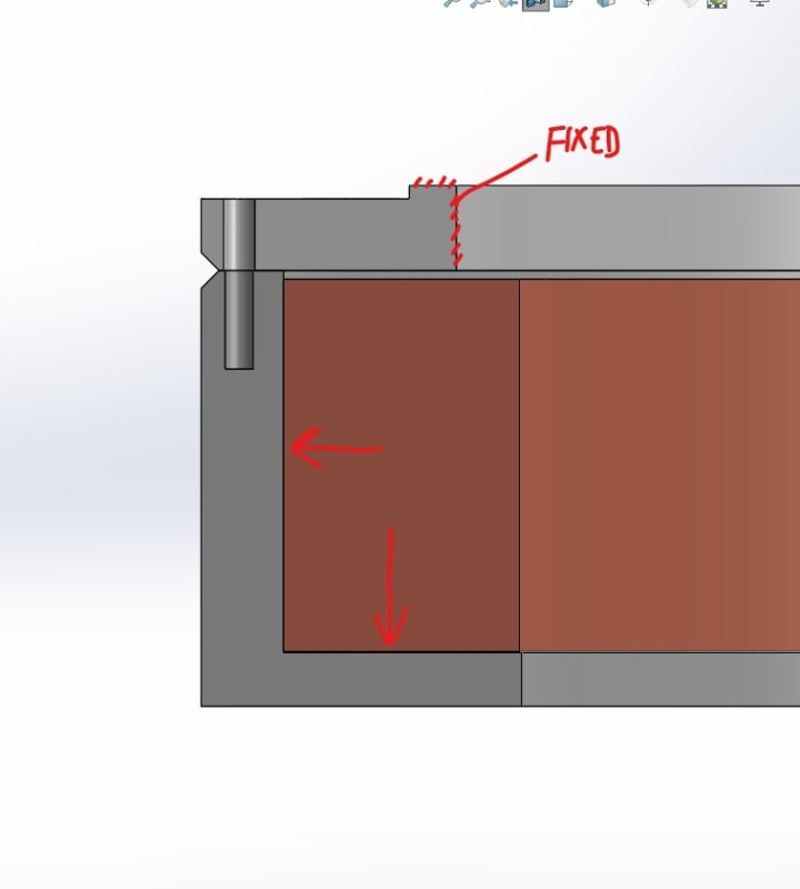
coil_and_bobbin_t3fzkh.jpg

cross_seciton_snip_mtc94x.jpg
 
Replies continue below

Recommended for you

hacksaw
I totally agree and will make sure we go over everything before implementing any new designs or testing.

desertfox
Great I am glad we are on the same page. I think I am going to propose the following revisions:
-Double the number of bolts to 56/ea
-specify Invar washers/spacers thickness such that the room temperature preload is maintained
-specify a room temperature preload that results in a separation force that exceeds the full attractive force while avoiding embedding into the aluminum cover
-specify 2D helicoils
-Make grip length at least 4 bolt diameters
-keep M6 diameter if all other conditions met

I like this because the covers can be modified and reused, the bobbins need to be replaced for revisions not involved with the bolted joint.
 
Hi Andre3

Make sure you specify a preload about 50% higher on each bolt over what you actually need, this will allow for the error in using torque to preload the bolts.
I would also specify a tightening sequence for the bolts which I think is tightening in a star pattern for a bolted ring. A couple of other points, one if possible lubricate the bolt threads before tightening bolts this should reduce friction losses, I would also if possible drill a pilot hole all the way through the base rather than have a blind hole, this eliminates trapped air when assembling bolts it also reduces the stress raiser which you normally get with blind tapped holes.
Good luck and happy new year!👍

“Do not worry about your problems with mathematics, I assure you mine are far greater.” Albert Einstein
 
Andre & Desert Fox

would a low strength Loctite help in this situation
 
Hi mfgenggear

Not sure how adhesives fair in a vacuum.😀🤪

“Do not worry about your problems with mathematics, I assure you mine are far greater.” Albert Einstein
 
There would be no advantage using an adhesive since the screws do not unscrew loose.

Ted
 
Hi Andre3

I have run a quick check with some of your proposals and I think you would be okay with 56 bolts at M6 to achieve correct clamping at 3K. If you have 8KN preload at the cooled temperature then the joint would be okay but that would mean a bolt preload of around 15KN at room temperature to allow for the bolt preload loss during cooling. (based on your last set of calculations posted on the 30th December).
At 15KN you would of course,according to my earlier calculation embed the bolt head in the Aluminium alloy, so you would need washers as you proposed to spread the load and prevent that but in using said washers what impact will that have on the bolt and joint stiffness?
In addition can you physically fit 56 bolts and washers on the given flange diameter?
If you can then this would be the easiest way to modify the current design as it stands and I believe you could use the 1.5D inserts although going to 2D is conservative but only if you use up the additional threads with a longer bolt and then its back to joint and bolt stiffness.

“Do not worry about your problems with mathematics, I assure you mine are far greater.” Albert Einstein
 
Up-size the screws. The screw capacity can increase by the square of the diameter change.

Ted
 
The screws aren’t the weakest part, the limiting factor will be the tapped aluminium alloy and the helicoils, the design of the joint should allow the bolts to fail in preference to the helicoil inserts, now in the failure above that happened, the 1D inserts failed and the 1.5D didn’t according to the OP. That said there might be room to increase the bolt size it depends on the sizes of the magnet housing and whether they can physically fit in.

“Do not worry about your problems with mathematics, I assure you mine are far greater.” Albert Einstein
 
Yes, but
Larger screws require larger, stronger threads.
Are helicoils necessary?

Ted
 
I once solved a problem. The impeller hold down bolt on a pump was failing. They couldn't increase the diameter because it would interfere with the keyway on the shaft. Their solution was to change to a hex shaft (no key). I suggested changing to a fine thread bolt. At 1/4 inch, the fine thread bolt was 70% stronger. Much money was saved that day.
 
Are helicoils necessary?

yes, much stronger then the aluminum parent material threads
 
But the helicoils failed. Ultimately the helicoil is threaded into aluminum thread.
Helicoils are good in aluminum for frequent assembly and disassembly of fasteners. A case could be made for spreading the thread loading.

I would prefer coarse threads in aluminum.

Ted
 
the helicoil's failed because the wrong length was specified see this link copied from the OP's post 30.12.20 it gives pull out loads for the inserts, the design used the M6 * 1 insert.
We need input from the OP really to see what can physically fit in the existing housing, the problem with increasing screw size means the bolt might become stronger than the internal thread and we don't want that, it better that the bolts break as opposed to stripping the internal thread. Even with a bigger thread you still need the preload that I posted earlier because a lot of preload will be lost on the cooling cycle but if you change the screw size then that effects the stiffness of the joint and screw stiffness and without going through all the calculations for the stiffness's of these components its hard for me to say one way or another how much better or worse it would be. If a larger insert cannot be fitted without changing the magnet housing envelope then I would say its better to try increasing the number of M6 screws first. Lets see if the OP comes back with more information.

“Do not worry about your problems with mathematics, I assure you mine are far greater.” Albert Einstein
 
desertfox
Ivar has extremely low thermal expansion, note the figure from 29.12.20, so I will use invar washers of a specified thickness such that the room temperature preload is not lost. Think of the washer as taking up the ‘slack’ from the contracting aluminum. I will need to calculate the required thickness and add it into the stiffness calculations to make sure everything is still good. Yes I do have space to fit 56 M6 bolts comfortably.

Hydtools
The helicoils give better pullout strength because of the increased shear area for a given amount of thread engagement and will be a benefit here. An exception would be if the size of the bolts must increase and I can’t afford the space required for helicoils, then long engagement in threaded aluminum could work.

The bolt pattern is centered 8.5 mm from the edge of the structure so there is not much room to work with. I am not sure if I can push the size, I need to check the machinery’s handbook to try finding the recommended minimum edge distance. Circumferentially I can also do 56 M7. I still prefer the smaller bolts if possible, I think they will be more desirable from a stiffness prospective and will give me more clearance above the cover which will also be helpful.

I am going to try to work out the particulars tomorrow, I have written a script that helps speed up the calculations but I will need to make adjustments to account for the invar washers.
 
Another idea to look at is using a thread forming tap instead of a thread cutting tap. It produces no cutting chips and creates improved thread quality.
For what it's worth:In my referenced product I have 18 each 5/16-18 screws on a 5.5 inch bcd in the center of a 0.5 wall thickness (5 inch id, 6 inch od cylinder). The 1/4-20 screws I started with broke during testing.

Ted
 
Hi Andre
Yes I agree with what you have written, normally as a rule of thumb the edge distance wants to be 1*D as an absolute minimum better figure is 1.5D, I assume from your post that the wall thickness is only 17mm that the helicoil is sat in? In which case I would stick with the smaller size.

“Do not worry about your problems with mathematics, I assure you mine are far greater.” Albert Einstein
 
desertfox
The wall thickness is actually 18.4mm, why the bolts are not centered is still a mystery to me. Since I would prefer to reuse the cover if possible, I am somewhat tied to an edge distance of 8.5mm.
 
hydtools
I like to use forming taps when tapping small holes in C101 copper especially, without flutes the taps are much stronger and have a tendency to not break off. I have never tried them in aluminum or with anything larger than an M4 but I will look into it.
 
Hi Andre3

Well I am in agreement with using the M6 screws/bolts its the easiest way to modify the existing design, as you said the other day though you need to include washers to spread the load under the screw / bolt head.

“Do not worry about your problems with mathematics, I assure you mine are far greater.” Albert Einstein
 
I wrote a script that uses the NIST cryogenic material data ( to calculate the separation force from room temperature down to 3 K for varying washer thicknesses, preloads, etc. . It works and I am closing in on the final design but I am a bit confused on how to specify the preload and further the torque wrench setting.

I plan on lubricating the threads with cryogenic grease, should I use a nut factor of .2 (Inconel bolt on 304 helicoil threads)?
If specify the torque setting to give a initial preload of 50% higher than needed, will I need still need to be at least 25% away from embedding in the aluminum? Does this already account for 10% loss from preload relaxation?

Between the nut factor and torque wrench uncertainty it seems like a bit of a shot in the dark for making a safe design. On the high end of the joint force I have to avoid embedment and on the low end I need to prevent separation with a good safety factor, with so much uncertainty I am concerned.
 
Status
Not open for further replies.

Part and Inventory Search

Sponsor