Continue to Site

Eng-Tips is the largest engineering community on the Internet

Intelligent Work Forums for Engineering Professionals

  • Congratulations KootK on being selected by the Eng-Tips community for having the most helpful posts in the forums last week. Way to Go!

Aluminum Weldment Design Help 4

Status
Not open for further replies.

Andre3

Mechanical
Mar 2, 2019
53
I have recently moved from a mechanical design role into engineering at my small R&D company figured I would try reaching out to you folks for some help and direction as I do not have other colleges to consult with. I am looking to design a weldment between two 6061-T6 components supporting a very strong solenoid magnet. This had been a bolted connection but the bolts failed after the system was overloaded and now we would like to weld them together for a stronger, permanent connection. My thought was to chamfer the parts to make for a groove weld to hold them together but I am mostly unfamiliar with weldment design.

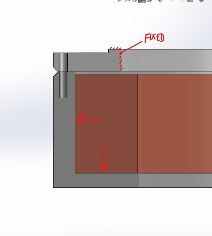
From what I have seen it looks like to be conservative I can expect the welded area to behave like 6061-O which is dramatically weaker. There is an axial magnetic force of about 250 kN downward and an outward radial force that is still being evaluated, for now I am treating it as 0.5 MPa acting on the inside wall of the support. Where should I start with evaluating the stress experienced at the weld and how it will behave? I have attached some snips of a simplified model for discussion.
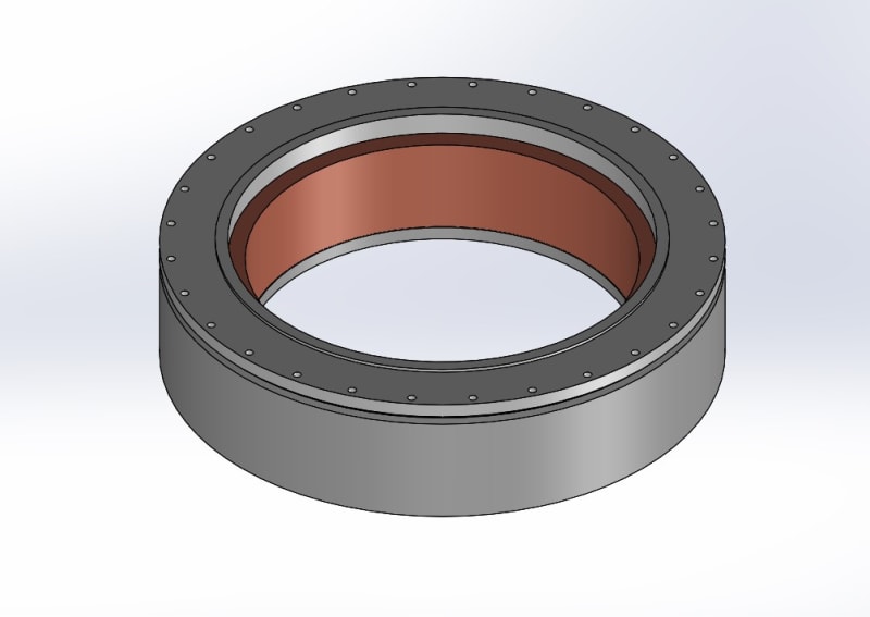
coil_and_bobbin_t3fzkh.jpg

cross_seciton_snip_mtc94x.jpg
 
Replies continue below

Recommended for you

Hi. Andre3

Well I haven’t got the values of the expansion coefficient but I believe the Aluminium alloy contracts more than the inconel bolt and you cannot keep the inconel in contact with the aluminium and therefore the bolt preload ends up at zero, you also say the joint separates which in my book means there is no load on the aluminium components.
If you have some calculations could you share them? The inconel bolts should be okay at -250 degrees C but I have no info at the -270 C which is where you are at. (Think I have mentioned this before).
Just out of curiosity what are you preloading the bolts too? If the preload is to high initially then the aluminium alloy will be yielding under the screw head and that will mean that the preload value will not be what you intended but something much less.
When you say that you have a 4-5KN loss of preload at room temperature, I take to mean that using the linear coefficient of expansion value that’s given at room temperature you have a 4-5KN loss of preload.

“Do not worry about your problems with mathematics, I assure you mine are far greater.” Albert Einstein
 
Hi Andre3

I am convinced now the problem is caused by the Aluminium clamped parts contracting during cooling to the point were the the inital preload generated by bolts on the clamped parts is reduced to zero because the linear expansion coefficient of the Aluminium alloy is greater than that of the Inconel, at this point the magnetic force is transferred to the bolts but because the load isn't equally shared the bolts fail sequentially. I had a look at the link which I have provided below dealing with compound bars.

“Do not worry about your problems with mathematics, I assure you mine are far greater.” Albert Einstein
 
Since it appears the low operating temperature is causing the bolts to lose tension maybe another approach is to use friction to hold everything together. If a shoulder bolt were installed with a close clearance to the bolt hole and counterbore then as the unit cools the aluminum will shrink and form an interference fit on the shoulder of the bolts. This will also make the entire assembly stronger because it eliminates the diameter reduction from the threads. I don't know that this would work if there were a gasket or seal involved as it still wouldn't be able to maintain compression.
 
@ Hydtools I think I might be able to get away with M7 bolts (They will be custom made anyway so an odd size is fine) but since the aluminum will need to be Helicoiled I don't think I would have the thickness in that area to go any larger.

@ desertfox I will make some notes on my estimation of the preload loss from cooldown and post them. The surface of the cover was pretty heavily marred so there was definitely local yielding which is not helping the preload situation. I have to just estimate what the bolts had for preload since they were not controlled at all during installation. I have been using 8 kN as a room temp preload estimate but I will look more closely at that to see if it is reasonable. That pdf looks useful also thank you.

@TugboatEng That is a very interesting idea, I haven't seen it done but I like it. There are some tight clearance applications where this could be very useful. No gaskets or seals to worry about but we need a pretty tight positional tolerance.
 
Hi Andre3

Thanks for your post.
Just an observation but I think the assumed 8kN preload is to low, if there are 26 bolts and you use 8kN preload that only gives a clampdown force of 208kN and the external load is 250kN according to your earlier posts. I estimate the bolts should be able to take a preload of about 30kN before yielding however that’s at room temperature and I haven’t given any consideration of the stress under the bolt head at that load so I don’t know if the aluminium alloy is yielding or not. I might have a look at the bolt head area and see what preload yields the aluminium but I still think you need bolts with a LCE that matches the Aluminium alloy at the required service temperature.

“Do not worry about your problems with mathematics, I assure you mine are far greater.” Albert Einstein
 
It does not appear to me that the load path from the magnets goes through the bolts.
 
Hi 3D Dave
where do you see the load path then? If the joint separates at -270 C Which I believe is happening I can’t see where else the load would go? Also if there is no load path through the bolts why are they breaking?

“Do not worry about your problems with mathematics, I assure you mine are far greater.” Albert Einstein
 
Andre3, for my suggestion to work, you would machine the two pieces together, bore the holes with the lid and body clamped together. This reduces the need to control the bolt hole location tolerance. The two parts will have to be clocked in that they be installed in the same orientation as machined. Think turn of the century precision oarts. A single dowel or some timing marks will facilitate this.

The weakness of my design as I speculate is that as the temperatures drop the aluminum will grip on to the bolt at a certain height and then both parts will shrink towards the center of that friction zone so they will shrink ways from each other. I'd you need the faces to seal this can cause trouble. An Inconel spring gasket with its lower COTE may be able hold a seal as the aluminum shrinks away.
 
desertfox - though I mentioned it earlier, I think that the core is not shrinking as rapidly as the housing, regardless of the information supplied. The bolts are failed in a manner that matches a pure tensile failure, which means not primarily bending, so the lid isn't shrinking radially and bending them. If radial shrink was the only force, it would not pull the short inserts loose and one last bolt would remain unbroken. There is a static magnetic load being applied, as shown in the arrows of the original post. In the latest post he says the cover was heavily marred - a condition that a high bolt tension load would produce.

 
Hi 3DDave

Well I thought at first the bolts were shearing due the shrinkage of the aluminium casing but has you say the bolts appear to be failing in tension and since I realised or believe that the bolts cannot prevent the separation of the joints due to the difference in expansion coefficient,then in my opinion the bolt will see the full magnetic load and possibly fail in tension one by one due to uneven load distribution, a heavy presence on the surface of the aluminium parts could be the bolts were over tightened at room temperature and possibly embedded into the aluminium alloy due to exceeding the aluminium yield stress.
Unfortunately it’s all guess work because we don’t have the expansion coefficient at the cryogenic temperature so my guess work is based on the coefficients at room temperature which would indicate to me that the aluminium alloy contracts and losses contact with the inconel. The magnetic force can then pull tension directly on the bolts and there might be some bending on the bolts which could also be tensile bending.

“Do not worry about your problems with mathematics, I assure you mine are far greater.” Albert Einstein
 
It's clamping a magnet made of a material that I expect has a lower CTE than the aluminum. The magnet pulls against the bottom of the bore in the aluminum, according to the initial diagram, so the bolts are not in that load path.
 
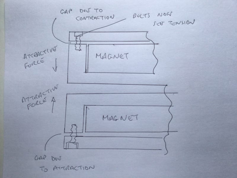
On the 22nd of December the OP posted a picture of two opposing magnets pulling at the base of the opposing aluminium housing, if the preload on the bolts is lost due to contraction each housing is being drawn to each other due to the attraction of the energised magnets, now he also stated the lids of the housing were held by brackets not shown but it’s clear to me that under that condition the load from the magnetic field will be transferred to the bolts

“Do not worry about your problems with mathematics, I assure you mine are far greater.” Albert Einstein
 
My understanding of the situation
FA714C30-99EA-42CB-B9B1-EBB41F78202B_wwciye.jpg


“Do not worry about your problems with mathematics, I assure you mine are far greater.” Albert Einstein
 
If they failed under magnetic load it would have been an explosion as the two magnets would collide. I've seen the damage a small tool can do near one of these; full magnet release would be catastrophic.
 
The casings are contained within another chamber read OP’s post 24th December, again if the bolts failed in tension and not in the load path then are you saying they failed during tightening? I doubt that is the case. So if it wasn’t during tightening and it wasn’t that the bolts were in the load path, then we’re did the tension come from?

“Do not worry about your problems with mathematics, I assure you mine are far greater.” Albert Einstein
 
Yes this was definitely a catastrophic failure, it was quite the event. The magnets are in separate vacuum chambers with an air gap so they did not collide with each other but instead slammed into the bottoms of their chambers. The energy in the coils was quickly dumped into a locomotive resister and amazingly the magnets survived. The heat shields were smashed and they put some good dents in the chambers but otherwise the hardware was alright.

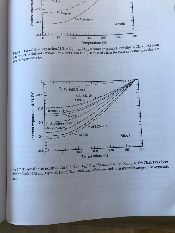
@ desertfox That is the right idea, notes coming on the contraction calculation. Keep in mind we know what the total contraction will be, the aluminum will shrink 0.435% and the bolt 0.238%, which should get around needing the CTE as a function of temperature.
 
Thanks Andre3

That’s a bit more of the puzzle solved. Without the CTE at -250C how do you know the contractions? I guess you are basing it on room temperature CTE.


“Do not worry about your problems with mathematics, I assure you mine are far greater.” Albert Einstein
 
@ desertfox I have the data in plots, tables, and software:

IMG_1532_vyhnj3.jpg


If we use the room temp CTE we would over estimate the total contraction quite a bit, almost zero contraction happens below 50 K.
 
" The magnets are in separate vacuum chambers with an air gap so they did not collide with each other but instead slammed into the bottoms of their chambers"

So it wasn't bolts failing one at a time. I knew this was a wild goose chase.

In literature it's called "the unreliable narrator."
 
Status
Not open for further replies.

Part and Inventory Search

Sponsor