Continue to Site

Eng-Tips is the largest engineering community on the Internet

Intelligent Work Forums for Engineering Professionals

  • Congratulations KootK on being selected by the Eng-Tips community for having the most helpful posts in the forums last week. Way to Go!

Aluminum Weldment Design Help 4

Status
Not open for further replies.

Andre3

Mechanical
Mar 2, 2019
53
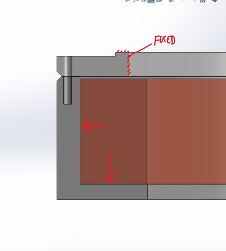
I have recently moved from a mechanical design role into engineering at my small R&D company figured I would try reaching out to you folks for some help and direction as I do not have other colleges to consult with. I am looking to design a weldment between two 6061-T6 components supporting a very strong solenoid magnet. This had been a bolted connection but the bolts failed after the system was overloaded and now we would like to weld them together for a stronger, permanent connection. My thought was to chamfer the parts to make for a groove weld to hold them together but I am mostly unfamiliar with weldment design.

From what I have seen it looks like to be conservative I can expect the welded area to behave like 6061-O which is dramatically weaker. There is an axial magnetic force of about 250 kN downward and an outward radial force that is still being evaluated, for now I am treating it as 0.5 MPa acting on the inside wall of the support. Where should I start with evaluating the stress experienced at the weld and how it will behave? I have attached some snips of a simplified model for discussion.
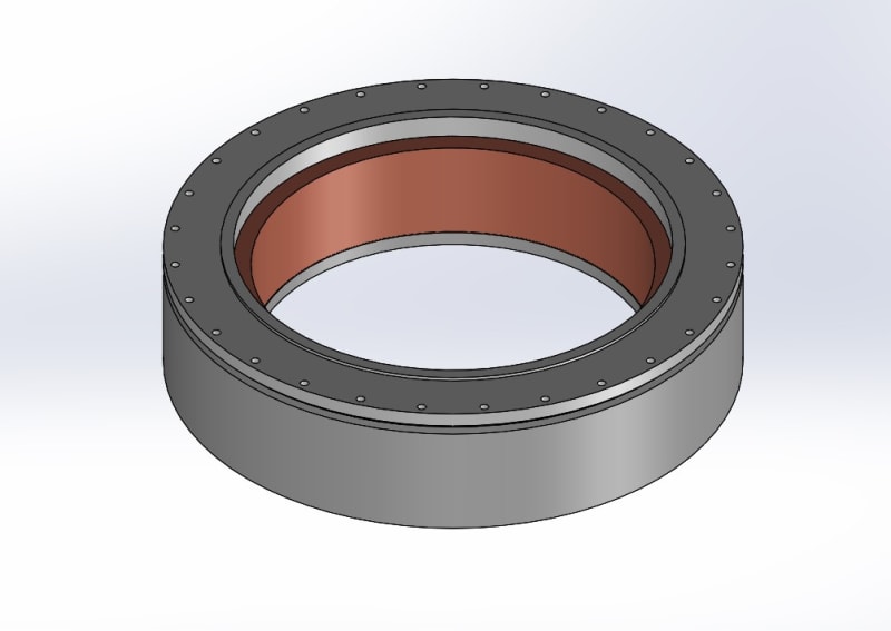
coil_and_bobbin_t3fzkh.jpg

cross_seciton_snip_mtc94x.jpg
 
Replies continue below

Recommended for you

I think I can tell why the designer is gone - is their supervisor and the design review team also gone?

(fixed typo)
 
Hi Andre3
Have a look at the links below, the first link on page 9 and 10 shows what an Inconel bolt tensile failure looks like. The second link shows the advantage of increasing bolt grip length.

Reading your latest post will respond later.


“Do not worry about your problems with mathematics, I assure you mine are far greater.” Albert Einstein
 
@ 3DDave yes and no, we are a very small group so the sr. engineer was almost entirely self regulated. Given the complexity of the system it is impressive how much he got right in the amount of time that it was done. We are changing things moving forward to prevent design misses like this, in the interim I am doing my best to move things forward and develop my own skills.

@ desertfox that is a great paper about failure analysis in general, even better that it discusses 718 bolts/studs. I think I will get some quotes for lab analysis, very valuable information.
 
@ TugboatEng The strain will remain fixed for a given force though, right? I can see how the strain would be reduced for a given amount of elongation, but when would that be the case? When we increase the grip length the change in length from thermal contraction will stay proportional so wont the stain remain the same?
 
If the only contribution is the differential between the bolt and the aluminum then that is correct. In that case then the bolt should never break and the short helicoils would not fail.
 
Your force isn't fixed. Your force varies greatly due to the differential thermal expansion. Increasing the length reduces the magnitude of that change in force. The aluminum has a higher CoTE so as it cools the bolts stay long while the aluminum shrinks causing them to lose tension. A longer bolt with more stretch will lose less tension for a given amount of shrinkage in the aluminum. When the bolts become loose they may not share the load evenly. Once the heavily loaded bolt fails, the zippering mentioned earlier begins.
 
 You
@TugboatEng The point I am trying to make from what I have learned is that the amount of shrink is defined by the length of the grip. A longer bolt must to pass through more aluminum, the grip length is equal to the bolt length. The amount they both shrink is a fixed proportion, no matter the length, the aluminum will shrink 0.435% and the bolt 0.238%. Maybe it is factoring in the joint stiffness that is getting me confused
 
If the preload is causing the bolt to stretch a finite amount, the longer the bolt the less each unit length of the bolt needs to experience strain. The total strain is the same but for a longer bolt the amount of pain felt is less.
 
Tugboat - I'm talking about the endpoint not changing, not that the force is invariant over temperature. Doubling the length of the bolt doubles the length differential due to temperature change, which doubles the overall stretch but, because it's over double the length, the strain is the same and so is the tension change due to temperature change. This applies in the case where the bulk material is of much larger section and therefore produces a higher "k" than in the bolt, a situation that seems to apply here. It also assumes that the Young's modulus is constant over the range; I think that is not true, but I also think the contribution isn't key to causing this failure.

Typically lengthening the fastener makes the joint more resilient by reducing the spring rate and allowing more vibration/shock energy to be absorbed and offsetting preload loss from wear/embedment, but I think that does not seem to be the underlying problem here.

What I believe is true is that this problem description is missing critical information that is required to evaluate the state of strain over temperature. It should be a simple linear equation. Were I more motivated I'd create a spreadsheet, but it's easy enough no one here should have trouble doing so.
 
Hi Andre3

I’ve been given this problem some thought and maybe you could test this physically at your place of work. If the Aluminium casing contracts sufficiently during cooling then all the bolt preload could be lost and that being the case, or the worst case, the bolts are loose and the casing can float, any external force acting like the magnetic force would transfer all the load onto the Inconel bolts and in addition to the external force the bolts would also experience the mass of the solenoid and the casing. Would it be possible to assemble a solenoid and casing and preload the casing bolts as the design stands at the moment and then check at the lowered temperature whether the bolts are loose or not? I have know idea what the mass of the components are so I might be way off port here. I do agree however that provided the 28 bolts share the 250KN evenly then the bolts should not fail. Contraction wise there is probably more going on in the radial direction than in the direction of the bolt axis and that’s why I think the bolts are shearing due differential contraction radially rather than vertically but additional tensile loading of the bolts will come from the mass of the components which is an unknown to me anyway, so the bolt failures might be a combination of tension and shear.
My bottom line I suppose, is that the bolt ,preloads have to compress the aluminium alloy casing lower than that of the free contraction that the aluminium would under go with the reduction in temperature,otherwise I think the joint will always fail. This is just my thoughts but I might have missed something in my thinking.

“Do not worry about your problems with mathematics, I assure you mine are far greater.” Albert Einstein
 
Daggumbit, I see my error now. Increasing the grip length increases the expansion. There is no difference in strain between short and long.

Another thought so maybe I can redeem myself, where does the force from the solenoid transfer to the plate? If the force acts in the center that can create a bending force about the bolts. A step ring on the that fits close to the bore would ensure the support is near the bolt circle minimizing the bending. The same step could also carry the shear as another user mentioned.
 
If the bolts completely lose their clamping force, a couple things might happen. You could get some impact loading on the bolts or, due to vibration while cold, the bolts could tighten and then they break while warming up.
 
let me just say it's awesome to be with a group that can help out each other.
If I may say finding the solution is not easy for this problem and it's way over my abilities.
however as a part of the failure analysis I believe a fish chart would be helpful.
to distinguish several issues at hand. It amazes me that that the bolts failed before the aluminum
housing. maybe a few changes may make a difference such as precise holes with shoulder bolts instead of fully threaded.
a more precise fit as not to allow the assembly to cause axial moment.
I sure some of the structural engineers can kick in comments on this. the threads are stress points.
and a fully shouldered bolt wit a slight press or very close slip fit may help.
I suggest maybe do an fea study on different configurations.
 
If the coil temperature rises during operation, will the coil expand axially more than the presumed smaller gap? Thermal expansion of a nearly incompressible material, epoxy and conductors, can generate very high forces. Would this cause the tensile failure of the screws?

Ted
 
Getting back to the original question, is there really any reason to not try welding the pieces together and not have any bolts at all, perhaps some blind pins for alignment?
 
@ desertfox the mass is negligible in reference to the magnetic forces, only about 50kg. I wish it were practical to cool the assembly down for testing the bolts but it takes a massive effort to assemble, and once it is together it is sealed inside a welded vacuum chamber so the bolts are not accessible. If we had a suitable container to bathe just the coil and structure with bolts in liquid nitrogen that would be almost as good, I might look into what that would take.

@ The force from the coil is simulated and fed into ANSYS mechanical as a body force density, I am not sure where the resultant is. There is definitely some bending which I think is a weak point of the design. I don’t have enough space in the bore of the coil to add any supports but I think that will be good to do in the future.

Thanks again! I am still going over the responses I will be back later today.
 
Andre3

Presumably, your coils are superconducting. Am puzzled by an early comment you made that the coils expand, that only happens in rare circumstances.
 
Andre3

I have been looking at thermal stresses in bolted joints and I have come to the conclusion that if you want have a bolted joint, then the bolts need a similar coefficient of expansion to that of the clamped components. Because the Aluminium has a much higher coefficient of expansion than that of the bolts, when it is cooled I believe the Aluminium contracts sufficiently to reduce the bolt preload to zero.
I don’t believe the bolts made from inconel can do the job especially with how low you are cooling, I think you need to find another bolt material


“Do not worry about your problems with mathematics, I assure you mine are far greater.” Albert Einstein
 

Andre3,
you may not have a stress problem at all if the coil supply is improperly designed.
 
@ hydtools The temperature of the coil remains approximately constant, it rises less than 3K. There is a radial force that needs to be better understood. I am also leaving the door open to the possibility that what we are using for thermal contraction properties could be incorrect.

@ IFRs I am interested in this as well, I am concerned about the annealed aluminum, cracking, and distortion. If anyone has thoughts I would love to hear them.

@ hacksaw Yes they are superconducting and generate a radial hoop force.

@ desertfox I took another look at the thermal effects of the joint and I think this could be the root cause. My estimates have a preload reduction of 4-5 kN from room temperature which could possibly have allowed for separation of the joint. Add to that brittle bolts and I can imagine the bending and shear they would experience to be enough to cause failure. If anyone has resources on thermal contraction effects on bolted joints I would like to pursue this more.

@ hacksaw what do you mean by coil supply?

I am beginning to think a redesigned bolted joint may be a good solution. Possibly keep the 718 bolts and use washers of low a low CTE material like Invar.

 
Status
Not open for further replies.

Part and Inventory Search

Sponsor