Continue to Site

Eng-Tips is the largest engineering community on the Internet

Intelligent Work Forums for Engineering Professionals

  • Congratulations KootK on being selected by the Eng-Tips community for having the most helpful posts in the forums last week. Way to Go!

Aluminum Weldment Design Help 4

Status
Not open for further replies.

Andre3

Mechanical
Mar 2, 2019
53
I have recently moved from a mechanical design role into engineering at my small R&D company figured I would try reaching out to you folks for some help and direction as I do not have other colleges to consult with. I am looking to design a weldment between two 6061-T6 components supporting a very strong solenoid magnet. This had been a bolted connection but the bolts failed after the system was overloaded and now we would like to weld them together for a stronger, permanent connection. My thought was to chamfer the parts to make for a groove weld to hold them together but I am mostly unfamiliar with weldment design.

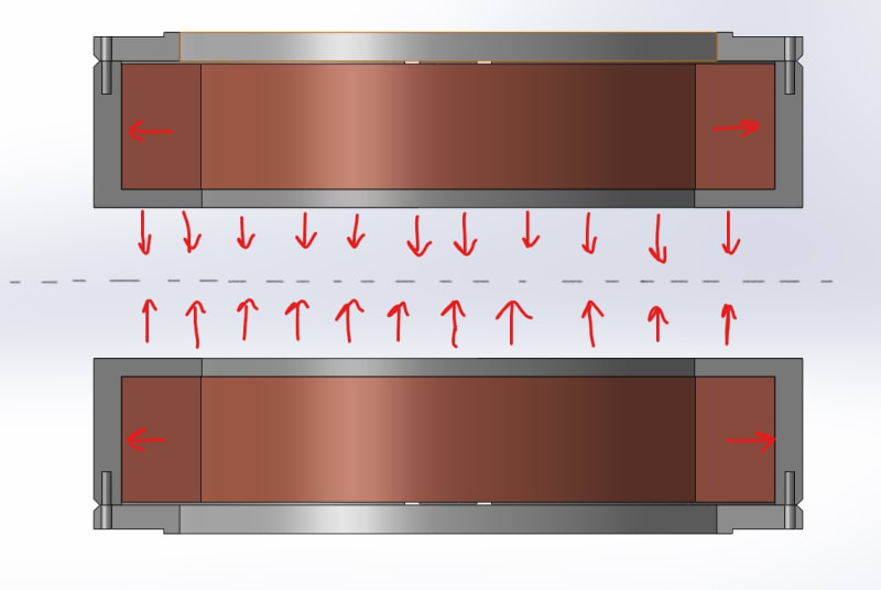
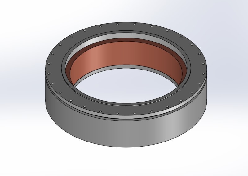
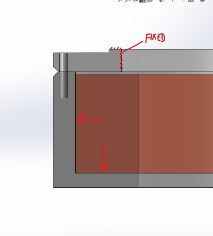
From what I have seen it looks like to be conservative I can expect the welded area to behave like 6061-O which is dramatically weaker. There is an axial magnetic force of about 250 kN downward and an outward radial force that is still being evaluated, for now I am treating it as 0.5 MPa acting on the inside wall of the support. Where should I start with evaluating the stress experienced at the weld and how it will behave? I have attached some snips of a simplified model for discussion.

coil_and_bobbin_t3fzkh.jpg

cross_seciton_snip_mtc94x.jpg
 
Replies continue below

Recommended for you

Here are some images of the bolts:
IMG-2500_vx9nlj.jpg

IMG-2503_kazebi.jpg


This is what the they looked like during disassembly:
IMG_1174_adqhtp.jpg


you can see on average they broke very close to the joint interface.

This also shows the steel flat and lock washer that have no place being there.

@hydtools would long bolts and nuts increase the strength?
 
Looks like tensile failure through the thread root.

Ted
 
At those temperatures, differential shrinkage between the bolt material and the joining parts may have created enough tensile strain to break the bolts. Do the the bolts and the other parts ahve the same reaction to your temperatures? A more basic question: are the bolts suitable for such temperatures or are they embrittled? Did they break as the temperature was decreasing or as it was increasing? Do the joining parts "feel" the temperature swings before or fater the bolts?
 
It certainly looks like the aluminum shrank more than the magnet material putting the bolts in tension. I expect that the contraction is not linear for any of the materials involved, but what is the CTE for the magnet and how long it? Also to keep in mind, the aluminum cover is also shrinking radially without constraint of the magnet while the shell is constrained by the magnet - this adds a shear load as well.
 
Hi Andre

Thanks for the photographs, those bolt failures do look brittle and did you get any documentation with the bolts because Understand Inconel bolts can suffer hydrogen embrittlement.In addition my last post I mentioned a working temperature limit of -250 and not -270 degrees C which might not help your cause.
However coming back to the bolt failures if the Aluminium as a higher coefficient of linear expansion than that of the bolts, I would have expected the bolt preload to reduce whilst cooling and thereby reduce the tensile stress in the bolts,in line with a comment you yourself made on your post dated the 18/12/20. Other than the mass of the solenoid what other forces could induce tensile stress on the bolts? You mention the force of attraction of 250kN but I cannot visualise the set up. I suspect that the bolts have failed in shear due to differential thermal movement between the cover and the container.
Through bolts with nuts are usually better for a joint in my opinion, particularly if there is cycling tensile stresses but if those bolts are failing in shear then I don’t see how they would help in this case, of course this is only my opinion and maybe you should get those bolts checked at a laboratory as they will give you a much better answer.


“Do not worry about your problems with mathematics, I assure you mine are far greater.” Albert Einstein
 
Is it necessary to fully contain the magnet? Would it suffice to have end plates and long screws threaded into the opposite plate. The screws would have thermal characteristics similar to the magnet and no interfering aluminum.

Ted
 
Thanks everyone for the input.

The operation of the magnet starts with cooling everything down to its base temperature, around 3K, over ~30 hours. Then current is slowly supplied causing the magnetic field to rise. The temperature of the magnet also rises during operation but only slightly, never exceeding 6K, which negligible effects compared to the magnetic forces. The coil is wound and impregnated with epoxy, axially it contracts more than the aluminum and radially it contracts less. At room temperature there is a gap between the structure and the coil which closes during cooldown. The aluminum structure contracts more than the Inconel bolts, 0.435% and 0.238% respectively, so the bolts are loosing tension preload as it cools down.

The coils are attracting to each other, that is where the 250 kN axial force comes from. There is also radial force outward on the structure, the coil wants to expand, but this is more tricky to evaluate, I am trying to sort that out now.
two_coils_and_vectors_qmxocw.jpg


I don't have anything that came with the bolts but I have reached out to the manufacturer to see what they say. This material is advertised as remaining ductile at cryogenic temperatures and has been used in other structural applications at low temperature so that doesn't feel like the solution to me. The bolts tested in tension to failure look very similar to ones that failed in service:
IMG_1500_oksp60.jpg

IMG_1498_1_oq9epi.jpg
 
@htdtools yes we coil needs to be contained radially and the structure helps with cooling.
 
28 bolts ? ~ 2000 lbs per bolt axial load?
What is the estimated "overload" load. tTere's your target for bolt preload at operating conditions
What size bolts ?
Are the axial and radial loads DC or AC ?

The attached image shows the cover with a close fitting ( nominal .002" Ø clearance for assembly ) pilot to resist the radial load applied to the cylinder.
Note there is only one mating face on the cover an cylinder.
Is there some kind of a gasket (indium) or sealant used ?


The bolt holes are much deeper for longer bolts. Bolts with grip length >7X the diameter would be a nice starting point, but through bolts would eliminate having to tap deep holes.
The bolt holes are counterbored deeply so the bolts don't handle shear loads. The bolts should have solid shanks in hte shear plane anyhow.
 
 https://files.engineering.com/getfile.aspx?folder=6bb12bff-adcd-425b-ab5b-2a09ed407dd9&file=cryo_weld_.PNG
Hi Andre3

I am studying your latest post and thanks for that, before I respond in any more detail I have several important questions and these are :- are the magnets arranged as shown in your sketch ie one mounted vertically above the other? Are the fasteners in both magnets failing are just the one in the top or bottom position?
Struggling to understand how the solenoid can can contract more in the axial direction but less in the radial direction when compared with the Aluminium?
Can you not just put a bigger clearance radially between the solenoid and aluminium body?

“Do not worry about your problems with mathematics, I assure you mine are far greater.” Albert Einstein
 
Longer bolts with may stretch more and be a bit more forgiving. Were longer bolts ever used or specified?
 
@ Tmoose
The overload would be 300 kN, so you propose that the bolts be preloaded so they will have 10.7 kN of tension when cold and ready to operate?
The bolts are M6x1.0 Inconel 718 age hardened.
The magnet is charged with DC current, I am not sure if that answers your question.

I like the pilot.
There is no seal indium seal there, the entire assembly is in a sealed and evacuated vessel, 10e-6 mbar.
Long bolts have been a common suggestion, it hasn't clicked with me yet what makes them so beneficial. Is it simply that they elongate more at the same load compared to a shorter bolt preload?

@mfgenggear
Good link thanks, they also list Inconel 718 for cryogenic service so that is encouraging.

@ desertfox
Yes the orientation is as shown and they both failed. The bottom assembly had the short helicoils installed on all threaded holes, 14 helicoils ripped out and 14 bolts broke. The top assembly had appropriate helicoils and all 28 bolts broke.

The images of the assemblies I have posted are simplified, the coil winding has spacers on the top and bottom made of composite which contract more than the superconductor-epoxy matrix of the coil.

The contact that the coil makes with the structure is part of the cooling path so we need to be making contact there to get the coil temperature low enough. In the future the cooling can be done differently to avoid the need for the radial contact.

@IFRs
No long bolts have not been tested but seem to be a common theme.

 
I know less than most the point of the link I posted is at that low temperature the steel become very fracture brittle, and loss of physical properties.
the most that a cryogenic steels is rated for is -270 D F, and test have to be run which a charpy destructive test. I don't believe welding the aluminum will solve the problem.
I would suggest a failure analysis by a metlab, and may consider changing material of the bolts.
 
may have to go with larger bolts, to allow for the strength difference.
 
I'm wondering how the CTE for the materials involved were determined for the full range of temperatures seen in this assembly. Likewise how the strain calculations for room temp assembly were translated to operating temperature strains and material strength properties determined for the operating temperature.

How were any calculations done in the absence of this information?

In any case, a small test sample is easy to prepare - block of aluminum with an insert, aluminum block with a hole to match the cover dimennsions, and a bolt torqued as designed. Drop it into liquid helium to reach the operating temperature and see if it breaks the same as seen in the full assembly. If it does then the bolt is too brittle/strain is too much for some reduced strength. If it doesn't, then I'd say the estimate that the coil is shrinking more than the aluminum is wrong, but needs confirmation.
 
@ mfgenggear Yes I agree steels are not good for the temperatures we are working with but there is no steel in the assembly aside from the 304 stainless helicoils, the bolts are Inconel 718.
 
@3DDave

I was not involved with the design of the system and the designer is gone and with him so are many details of the process so I will do my best.

We have access to temperature dependent material property databases down to cryogenic temperatures such as cryocomp thermal analysis software and other sources that we use. The cryocomp software also helps with quick calculations of things like heat loads and length changes from thermal contraction as a percentage. The materials we use have been defined with these properties in ANSYS and have been used to analyze the system. As far as I can tell the bolts were not analyzed in ANSYS. So there was no consideration for the bolt strain at low temperature, or control of the room temp assembly.

We do not work with cryogens often but have done some thermal shock testing in liquid nitrogen and have a dewar. We could cool a test assembly to liquid nitrogen temperature and try to quickly transfer it to the Instron but I think the sample would heat up considerably before testing started. The thermal expansion curve is not linear at low temperature and is nearly flat for most materials from liquid nitrogen temperature to liquid helium temperature so that may still be useful depending on how warm it gets before the test starts.
 
Andre3, about the benefits of longer bolts. You need to think about the strain in the bolt. The length of the bolt is the denominator in strain so increasing the length of the bolt reduces the strain. In your case you have a specific amount of thermal expansion you must deal with. A longer bolt will see less change in strain over the range of conditions.
 
Status
Not open for further replies.

Part and Inventory Search

Sponsor