Main bearing loads
Main bearing loads
(OP)
Howdy,
Single throw crank shaft with articulated rods. 5 cylinder radial. I've balanced the crank inertia loads the best I can variable about 871.8 lbs with the CG moving out max .155 inch... I tried it doesn't get better than that. I'm guessing that's kinda rough but it's a big engine. 450in^3
Now what I'm curious about... I have an actual gas pressure plot from a nearly identical cylinder (It's form exactly what you would expect for a 4 stoke SI engine)It's peak pressure is 880psi! That results in a parallel cylinder force of 18,100lbs!!!
If I take the average pressure of that entire actual gas pressure plot for 720° I get 117.25psi.
and finally for fun my estimated IMEP is 214 PSI.
My only design reference that gets into this level of detail for determining bearing loads I could find... completely ignored the Peak pressure force looked to an "Average" force of which I cant derive from the table data how the "average" value was obtained.
Is that peak pressure a shock load that happens so fast the bearing doesn't really "see it"... other? I would like to understand their reasoning to make a sound engineering judgement for bearing selection.
Thanks!
RE: Main bearing loads
Most large engine use hydrodynamic journal bearings which "float" the shaft on an oil film pulled between the shaft and the bearing wall. EPI gives a nice summary of these bearings. The paper "Journal Bearings Subjected to Dynamic Loads: the Analytical Mobility Method" illustrates how complex the analysis/design/specification of such bearings can be. For what it's worth, I see no mention of averaging shaft loads in the paper's calculations. That being said, it does take time for the oil supporting the shaft to "leak" radially to the lower pressure area on the unloaded circumference of the shaft or axially out the end of the bearing, so perhaps there' a rule of thumb that permits smoothing of the cylinder pressure waveform (it's unlikely to be a simple average, however, and would most certainly include RPM).
Once you answer the questions above, I may be able to provide additional input.
P.S. I don't know how useful it is given there are no five-cylinder radials in the list and old engines didn't likely produce pressures as high as modern engines, but the paper "Crankpin Bearings in High Output Aircraft Piston Engines" provides tables describing the bearings and loads associated with a good number of old radial engines using articulating rods.
RE: Main bearing loads
A1. Cylindrical Roller bearing has been traditional used in Jacobs radials. However without "smoothing" of the wave form I can find none that are capable that can fit in the assembly. I initially thought I would end up with a Hydrodynamic bearing, and intend to do so with the "crank pin"... but have been advised against it for the mains largely because of traditional usage of rolling element bearings in radials.
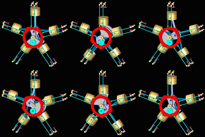
A2. In that animation... I would imagine there is a "main bearing" mounted behind the yellow sun gear in the middle in front of the grey master rod, along with an accompanying bearing on the far side of the master rod. "main bearing" for this Thread to be the bearing which supports the crank assembly to the engine case. These two main bearings support the radial components of the rotating mass inertia, and gas pressure loads. The before mentioned "crank pin" bearing would be the interface between the Grey crank assembly, and purple master rod. For reference: A third axial "thrust" bearing not shown in the animation above deals with propeller thrust... but I'm not to that one yet... besides it's forces are relatively mundane in comparison.
A3. Liston, Joseph. "Aircraft Engine Design" First Edition. McGraw-Hill 1942. Specifically Figure 5-21 describing Front and rear main bearing polar diagrams. Through the book, he designs around a theoretically constructed gas pressure indicator card whose peak force is roughly 4580lb and Ave Force is 1807 lb... much lower than my machine.
Liston has a fairly complete Hydrodynamic bearing design section that I'm pretty familiar with. Just looking for proper method for inputs of their design.
Looking at "JOURNAL BEARINGS SUBJECTED TO DYNAMIC LOADS: THE ANALYTICAL MOBILITY METHOD" I don't see their input gas pressures/inertial forces.
Your last "Crankpin Bearings in High Output Aircraft Piston Engines" Very nice... that will take me some time to digest. Have a look at table 11 and surrounding content. Wow... those pressures are up there. Maybe my problem is assuming that I can find a COTS bearing for the application.
My engine isn't a multi row radial, so the possibility going to hydrodynamic mains exists...In fact I'm pretty interested in the idea just never seen it done in a radial... nor have a I seen places like King bearing produce a full circle bearing for a bore...as the case doesn't split on the bearing bore like it does for typical Horizontally Opposed aircraft engines.
RE: Main bearing loads
I realize that your situation has more than one cylinder ... but it's only got one cylinder with anywhere near peak cylinder pressure at a time. Every other cylinder in the top-dead-centre order is a firing, i.e. the firings are 144 degrees apart.
RE: Main bearing loads
Thanks!
One of the ones on the radar right now is a 6314. I've got 2 other threads asking about how to mount such a thing. Is it a press fit into the housing and onto the crank? Is the case split?
RE: Main bearing loads
@RodRico... Yeah those and the one from timkin are telling me it's a no go with the max force. As Brian there illustrated there are some issues building it up with a deep groove. I'm actually leaning towards some Timkin Roller bearings.
RE: Main bearing loads
Tapered rollers work ok in rear-end differential housings and transmissions and the like, but those operate generally pretty close to uniform temperature - no foreseeable huge thermal stresses - the temperature of a rear axle housing might change as a whole but it doesn't have internal bits and pieces that are significantly different from ambient because of combustion happening inside.
RE: Main bearing loads
I've given serious consideration to two taper roller bearings as the propeller put an axial load on the assembly... but figure I'll stick with one deep groove in the nose of the engine for end to end location... let the other two "float" axially.
I was thinking cylindrical roller bearings (not taper). They come apart just like taper roller bearings so I can assemble the unit easier.
RE: Main bearing loads
Get a hold of "Analysis and Lubrication of Bearings" by Mack and Shaw for good descriptions of radial engine bearings.
Many of the master rod bearings were a floating shell arrangement with an oil film on the O.D. and I.D. There are exceptions, of course.
RE: Main bearing loads
Just looked at his Hartog link. I can understand that the gas pressures equal out as far as vibration,That's one thing... but the stress path from the top of the cylinder to the shaft is still through the main bearings. Are you saying the bearings would not "feel" the gas pressure load(s)?
I'm thinking of it like this... If I motored the engine up to it's RPM with an external motor... that would be how I would balance the rotating mass (pistons, wrist pin, con rods, crank) I got that under control. But with actual combustion that force is getting sent into the structure of the cylinder, bolted to the crank case, radially through the main bearings, into the crank shaft.
Trust me... If I'm wrong I would be ecstatic because that's a MUCH smaller (cheaper) bearing. Will look for your Mack and Shaw when I get home.
RodRico I'm all for you method once to get "out" of the engine but inside I would be a little more concerned... difference between a rotor mast support bearing vs the engines main bearings. You mentioned a prop... Water or Air? If Air... what shaft/hub you using for the prop mount?
EDIT: EHudson, I ordered Mack and Shaw.
RE: Main bearing loads
The peak pressure does matter for bearing calculations. With journal bearings this peak load is a major determining factor in rod bearing area determination. Main journal bearing sizes are often based on both crank strength and torsional stiffness.
RE: Main bearing loads
You have anything you could point me towards re peak pressure... short of the book on its way?
RE: Main bearing loads
Transducer measured cylinder pressure. X0 it TDC. CR=8.5/1
So far this is the best Dynamic balance I've been able to attain. This does not include gas pressure!
RE: Main bearing loads
My engine is a six-cylinder, opposed-piston, cam-driven, two-stroke in which each cylinder produces four power strokes per revolution. This arrangement, shown in the left figure below, results in two cylinders on opposite sides of the engine firing simultaneously. The firing pair alternatives between a vertical pair and a horizontal pair. The middle figure shows the simplified CAD model I created for quick analysis of bearing stress. The model describes only two opposing cylinders in vertical orientation within the rotor assembly. The opposing pistons in each cylinder have been reduced to just their cam radius with a flat face to which 2,915 lbf (the product of my peak gas pressure and piston surface area) is applied. The bearing model (6202 selected without the 5x safety factor I mentioned in my last comment) was downloaded from the supplier and the material specified as ASTM 52100 bearing steel having 67 kpsi yield strength. All other materials are Maraging 350 steel with 295 kpsi yield strength (associated with 600F).
The right figure captures the result of static stress analysis in which all components but the bearings are hidden from view. I have also hidden the outer hosing of the most healily loaded bearing so it's balls are visible. The top plot shows bearing stress when only one cylinder fires. In this condition, the peak stress on the bearing is 23,212 psi, 1/3 of the bearing material's yield strength, too low for long term fatigue life of the bearing IMHO. The lower plot shows bearing stress when the two opposing pistons fire simultaneously. In this condition peak stress falls to 8,376, about 1/8 of the bearing material's yield strength, likely adequate for long term fatigue life IMHO.
This quick study illustrates an important phenomenon. Note the hot spots above the bearing balls in the top stress plot and compare them to the widely distributed load on the outer shell of the lower plot. Even with twice the loading being applied to the central shaft and the rotor of my engine, the peak stress has fallen by a factor of 2.77. Factoring in the doubled load, that's a 5.54 x reduction in peak stress.
RE: Main bearing loads
Static analysis of a bearing like in the far right is going to be VERY difficult to justify for anything other than a not rotating condition. Resultant contact forces in an analysis like that is going to have more to do with the size of the elements (mesh) than anything attempting to replicate a real circular contact patch from deformation. I would suggest a 2d Symmetric FEA, because the amount of elements needed to make a full blown 3D analysis would be HUGE to say the least because the size of the real contact patch deformation is TINY. With that said... where did you get that 52100 Fty is 67ksi? Maybe dead soft annealed. It's closer to 295ksi in a usable bearing state. Static load isn't even the limiting factor in a bearing...usually. With that said with the numbers below it's exceeded the raceway static load capability.
Where did you get your 5x safety factor concept from? Again applied to above model... absolutely meaningless for bearing selection.
How long do you expect the engine to operate before bearing failure is THE problem:
Now I'm guessing I'm missing some aspects of operation of this type of engine... so just looking at Peak piston face force of 2915 lb, assuming the line of action is "small angles" to the center of the bearing I think you said it was a 2 stroke so I put it up to 11kRPM as a guess and I got 19 minutes before the bearing is at a 10% chance of failure life... not safe. Even if it's a model there is a lot of machining that's going into a project like this... those bearings loose it... that's going to destroy the engine. If it were me... I would cry. You got some work to do.
RE: Main bearing loads
This is a single cylinder engine with a balance shaft, so some of the mechanical balancing loads pass through the main bearings, but just look at the combustion loads.
From SKF, the basic dynamic load rating is 27 kN and static rating 15.3 kN. The limiting speed is 13,000 rpm ... engine redline is 11,000.
I get 40 hours rated L10 life at 8000 rpm (top gear at 100 km/h is in that range). Mine has about 60,000 km on it. Obviously the combustion load is only seen for several crank degrees once per two crank revolutions, and since the piston acceleration is opposing the combustion forces at high revs, that helps some, and since that part of the life equation has an exponent on it, it probably actually helps a lot. If the stated load is only seen for 10% of the operating cycle, that changes it to 400 hours rated life ... probably 40,000 km at wide open throttle. This bike is only ridden at wide open throttle ... it only has 12 horsepower. The MTBF life is much greater than the L10 life, and this calculation is probably rather conservative. Seems in the ballpark, though.
RE: Main bearing loads
Cylinder bore is only 1.078 in and stroke while ports are closed is only 0.342 in. Peak gas force is 3,057 psi (28:1 CR with max equivalence of 0.46), and max rotor speed is only 2,626 RPM (driving the propeller directly).
I understand bearings are dynamic devices. I used static analysis at the worse case condition to get a feel for the loads resulting from my opposed-cylinder arrangement with no mechanical imbalance (in theory). From the analysis, it's clear the arrangement has great impact on the stress on the bearing. The mesh I used isn't terribly coarse. The minimum element size (0.01in) was selected by Solidworks based on the minimum radius in the design. I only use 2D symmetric analysis when I need to. This particular analysis only takes about an hour to run on my analysis machine (12 cores/24 threats at 3 GHz), and I'm free to work on my other less powerful workstation while the analysis runs.
I think I got the yield data from the "MakeItFrom" web site, but can't find where. Starting over, SKF says they use 100Cr6 which has 88 - 100 kpsi tensile strength in the hardened state according to MakeItFrom. Looking the same material up on MatWeb, however, results in 334 kpsi tensile strength and 247 kpsi yield strength. My mistake. I should have questioned the low number I found on MakeItFrom. I'll update my material properties per MatWeb.
The 5x safety factor was applied to the shaft diameter and I explained it's origin in an earlier comment: "In the cell where I specified the 5x safety factor, I have a note that says "required to force selection of the same bearing as the Honda GX200 engine which produces slightly greater HP and torque." The FEA analysis doesn't include that safety factor.
Since you are so quickly able to evaluate the performance of my bearings, I assume you have solved the problem of selecting yours. What bearing did you end up selecting?
RE: Main bearing loads
This link concerns itself with many combinations, but not quite Ball on race.
https://www.amesweb.info/HertzianContact/HertzianC...
The bearing manufacturer's load ratings take that into account.
There are host of "factors" that need to be stacked up to properly de-rate the bearing and solve for a reasonable life estimate.
I'd pay close attention to The "fatigue" load, and the lube cleanliness factors.
RE: Main bearing loads
Like Brian said "combustion load is only seen for several crank degrees once per two crank revolutions" He's absolutely correct... It's just I don't have a sound engineering source stating how to deal with that. Empirical on his bike is pretty tempting but I would LOVE to have a look at a Honda engine engineers design notes.
My references left me hanging in their explanation of going with an Average force instead of peak force for gas pressure.
If I work backwards from expected engine performance and use IMEP I get about 215 PSI as a "whole engine" average. If I take my gas pressure force from above and average... make a rectangle with the same area as the area under the curve I end up with 117 PSI. If I could justify using either of those two numbers instead of my peak 879.5 PSI that would make for what I would consider a "reasonable size" bearing for my packaging issues... and "looks right" when compared existing radials. All I'm doing is using Typical L10 life knock down ratings based on speed and load, along with a 2.0 "Extreme and indeterminate shock load" factor as Published in my Liston reference above.
One I haven't tried yet is only average the pressure for the crank angle range the pressure is "on the move". That would give me a little higher area average... probably a little more inline with IMEP.
Again, someone has to have figured out how to calculate this with a verified/published model. <- what I'm looking for.
RE: Main bearing loads
Barring manufacturing variance (which I cannot estimate at this point), my engine has no imbalance. It has only gas pressure, and because it is applied equally on opposing sides of the rotor, it is primarily manifest as uniform compression force on the outer bearing race and the shaft. From my FEA work these forces appear to be spread reasonably well across the bearing races.
I think much of the reason for confusion in regards roller bearings is the familiar engineering details are buried under ISO 281 standard language (aka "bearing parlance"). The NSK document "Dynamic Load Rating, Fatigue Life, and Static Load Rating" and the NASA document "Rolling Bearing Life Prediction, Theory, and Application" assist in understanding the basis of the language in normal engineering terms. I believe the averaging of load is justified under language relating to fatigue life not yield. That makes perfect sense IMHO insofar as peak loads are well under material yield.
In calculating your average force, don't forget much of the force on your pistons is translated into rotational force by the crank (or cam in my case). In my FEA runs (updated below with finer mesh and proper material properties), I assume the entire combustion event occurs at top dead center (detonation), the worst case (I obviously plan to control timing such that this doesn't occur, but it will likely happen now and then during testing). Note both plots below use the same color scale, and they clearly illustrate how little load is on the bearing races when opposed cylinders fire. Max deflection of any bearing component is 0.00047 in.
I'm now off to see if I can express my calculated bearing loads into "bearing parlance" so I can relate it to normal bearing specifications.
RE: Main bearing loads
Mack and Shaw showed up today. Same story... completely hung up on calculation, assumptions, and equations that are completely unneeded with CAD analysis. In multiple places they made mention of maximum and mean forces but gave no recommendation as to their deployment in bearing selection.
They mention Caminez and Iseler 1923 as being "The basic method of determining bearing loades for internal combustion engines and maybe they expect the reader to go check that out?
Being a little newer than my other book, the IMEP and Peak forces are in line with what I am working with so I know I'm in the ballpark.
There was mention of a "time weighted average" but again no mention of how to deploy it. It almost sounded like they were talking about a time weighted average through 720°... which I don't understand why that would be different than local to one cylinder... maybe I read it wrong. But I'm willing to bet BrianPetersen and his Honda example (10 Jan 20 13:05) is probably pretty close to the truth.
Having gone and looked at large Radials in museums I cant imagine that N 314 ECP bearing isn't an adequate choice for the forward main bearing.
RE: Main bearing loads
Look for instance at the Clear Energy Systems patents, for example US8567354-B2
PJGD
RE: Main bearing loads
EDIT: I just talked to one of the project leads. It's a P&W engine core they were tinkering with. I've got a call out hopefully I'll hear from the engineers.
RE: Main bearing loads
Below is a condensed version of SKF's bearing selection guidelines. Note the first statement under "Equivalent Dynamic Bearing Load" which says "When calculating the bearing rating life..." This tells you all those calculations relate to fatigue life not yield strength. Now jump down to the last statement of the left page and not where it says "High loads acting for short times (diagram 4) may not influence the mean load used in a fatigue life calculation. Evaluate such peak loads against the bearing static load rating C0, using a suitable static safety factor s0." The page on the right summarizes that calculation. Note that it is tied to yield strength insofar as the 4,200 MPa value for the "basic static load rating C0" is that which produces permanent deformation of .0001 x ball diameter. This small deformation results from the fact that the 4,200 MPa value is greater than the 2,000 MPa yield strength of 100cr6 bearing steel. Reading further down the page, you see that the peak load with no deformation uses a minimum safety factor of two which brings the 4,200 MPa value down near the yield strength of 100cr6 bearing steel.
Recall that the stress in the bearing is associated with Hertzian contact between the balls and the races and calculating the associated stress is terribly complex. That's why safety factors are common. Since the typical safety factor for engine components is at least six, a bearing specification would limit peak bearing load to 4,200 MPa / 6 or 700 MPa (101,526 psi).
Once you have the peak loads within the bearing's yield strength (derated by your chosen safety factor), you can go back to the "Equivalent dynamic bearing load" calculations on the left page of the figure above and use the results in bearing life calculations. I believe the "Rotating Load" calculation is most appropriate for engines, and it is not a simple average. I believe it instead approximates peak and average loads into a single figure. Since it's a fatigue calculation, however, a simple average likely won't cause too much trouble and may be common among experienced designers. In the end, I think you're going to want to keep peak loads below the derated static specification and equivalent dynamic load as required to attain the bearing life you desire.
In regards your confusion over "time weighted average through 720°," I would dispute the "time weighted" aspect in a crank engine (but not my cam engine) and assume the 720° figure relates to the two revolutions required to complete all four strokes (it would be 360° for a two stroke). In your case, you have five cylinders driving two main bearings, so I would calculate the min and max load through one revolution of the full engine then halve that figure for use in the equations for "Rotating Load."
P.S. I found the bearing discussion for MechDesigner (a cad program) to be the best I've seen thus far. It actually relates to calculations for a cam follower bearing, but it relates to any roller bearing and is clearly presented. The full set of SKF calculations tells the same story but is harder to follow IMHO. SKF does, however, provide several nice examples as well as some computer tools.
RE: Main bearing loads
The most highly loaded bearing is the master rod bearing. And yes there is large multi row radial engine that used hydrodynamic crankshaft main bearings. No tapered roller bearings used for crankshaft mains.
All large aircraft radial engines used SAE 60 weight oil.
Section view of R-3350 Wright Turbo Cyclone, showing the 3 rolling element main bearings.
http://www.enginehistory.org/Piston/Wright/Kuhns/C...