Continue to Site

Eng-Tips is the largest engineering community on the Internet

Intelligent Work Forums for Engineering Professionals

  • Congratulations waross on being selected by the Eng-Tips community for having the most helpful posts in the forums last week. Way to Go!

When can we call a beam a beam? 7

Status
Not open for further replies.

struggle67

Structural
Mar 29, 2013
116
Hi,

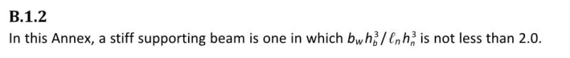
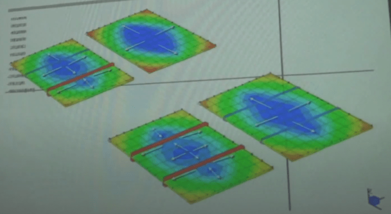
Someone told me that if a beam is not stiff/deep enough, it wont behave like a beam and attract all the loadings like a beam would. It will be like localized thickening of slab or like a beam in the column strip of a flat slab.

I think that he is right but I couldn't find any defination in the code. Why codes do not differentiate it? Is there any way to differentiate or should I just rely on FEM results?

And Wish you all HAPPY NEW YEAR!

Happy-New-Year-2021-1_y9xned.jpg
 
Replies continue below

Recommended for you

If a beam's stiffness is small in relation to others nearby, a load that is capable of being somehow transferred to an adjacent stiffer beam, for example through floor slab spanning action, might not put much load on the weaker beam. When multiple load resistance points exist, a load will be proportioned among them according to each resistance point's relative stiffness in relation to the given load. Of course a load transferred directly on to one beam, only has one resistance point, so that beam will take all of the load..

 
A "beam" is not defined, at least not a clear cut, by its geometry and stiffness. Rather the definition depends on its use - carrying and passing loads to its supports. For the flat slab, you can see it as many cross beams stitched together to form the plate.
 
Its all a question of stiffness in my view. A beam doesn’t know its called a beam and doesn’t care either. It will take whatever load its stiffness permits relative to other members around it.

I don’t recommend blindly accepting FE results. But once sufficiently interrogated, the FE answer is likely most accurate. From there, call members beams or anything else you like, just design them for the calculated applied forces.
 
I seem to recall that a beam was essentially a flexural structural item, and that was the only criteria.

Rather than think climate change and the corona virus as science, think of it as the wrath of God. Feel any better?

-Dik
 
You will see stuff like this floating around various places. It's from the Canadian concrete code as is used as a metric for determining when a beam is stiff enough to be considered a "stiff support" for the purposes of slab design. I certainly agree with the previous posters that stiffness relative to the surrounding stuff is the key metric. The equation below is an attempt at quantifying that geared toward old school design methods that predated the ubiquitous use of FEM software etc.

C01_ocflmj.jpg
 
In my own work, I'll often do this unless there's a compelling reason not to:

1) Assume beam action where I expect it.

2) Work out beam loads per #1.

3) Proportion beams per the loads from #2 and having a reinforcement ratio less that 50% of the balanced ratio.

In my experience, it often the beams that are heavily reinforced that are the deflection baddies.

Like any rule of thumb, it need to be applied judiciously and in recognition of exceptional circumstance.

 
Thanks for the list...

Rather than think climate change and the corona virus as science, think of it as the wrath of God. Feel any better?

-Dik
 
Thanks, Everyone,

I agree with you all on stiffness.

And I should have included this photo below earlier. Someone showed me that. There are two beams and 4 comparisons. The rigid beam is represented by a red line and the flexible beam is by the blue line.

Capture1_dfxhhf.png


In figure 4 (bottom-right) both flexible beams bend together with the slab (i.e. no/very little slab hogging moment at beams in the direction perpendicular to the beam). Most designers I know including myself (btw I am using 2D software) will not take that into account and will just always simply assume the beam is rigid and there is slab hogging moment at beams(just like in figure 3 (bottom-left). I think our assumption should be ok for ultimate strength design although it will require a lot of redistribution. I am worried that the slab will crack a lot more than I expected at service with a different pattern. That's why I was wondering when to consider a beam is rigid and how to account for that. I guess FEM is the way to go and for 2D, I will just use KootK's Canadian Code formula and steps.
 
KootK,

KootK said:

bw is beam width, hb is beam depth, ln is slab panel width and hn is slab depth.

May I know if that is correct?

Thanks
 
KootK said:
3) Proportion beams per the loads from #2 and having a reinforcement ratio less that 50% of the balanced ratio.

In my experience, it often the beams that are heavily reinforced that are the deflection baddies

50% of balanced is fairly heavy: neutral axis depth is 0.3* effective depth for 400MPa reo and 0.003 concrete stain, and into the territory where moment redistribution is limited or not permitted. Is it 50% of the code limit for tension-controlled, so more like 0.2* effective depth?
 
For the design of reinforced concrete flexural structures, the sequence of check has been - deflection, shear, bending.
 
r13,

Is it possible to give negative stars! Bending is always first.

Deflections 1st - only for those who use basic L/D ratios (and even then, L/D ratios in many codes are reinforcement ratio dependent) and do not calculate deflections, otherwise you need to know reinforcement quantities and a lot more.

Shear 2nd - how do you check beam shear without knowing the reinforcement content?
 
The beam is sized for deflection. So later it can only improve, will not getting worse.

One the size is determined, first check concrete shear strength without reinforcement, this is very important for slabs. If shear reinforcement is required, an estimate on the amount of shear reinforcement is made to ensure it is not excessive. If deemed excessive, increase member depth.

Up to this point, for simple structures, I don't ever need information from frame analysis.

The member that satisfies both deflection and shear, usually does not have problem to accommodate the amount of flexural reinforcement for bending. Otherwise, increase size again, but I know both deflection and shear will not be problem.

Sorry for my ignorance, I don't understand your second question. Once member size is known, don't you know how to check shear without flexural reinforcement? Are you relying on flexural reinforcement to increase shear capacity? It can, but so minimal, I'll utilize it only when the member size can't be further increased.

I think your approach is the way how prestressed concrete works though.
 
r13 said:
The beam is sized for deflection. So later it can only improve, will not getting worse.

As far as I've seen, concrete beam design proceeds like this:

1) Approximately design for deflection via span to depth ratios and other rough methods of that ilk. This is the best that one can do ahead of the flexural design because a detailed deflection estimate requires a knowledge of the reinforcing quantity and disposition that is generally only available after the flexural design has been accomplished. In my experience, designing reinforcing for deflection ahead of the flexural design is so rare as to be almost unheard of.

2) Design reinforcement for flexure.

3) Design for shear. In some jurisdictions, shear capacity is calculated independently of the flexural reinforcing while, in other jurisdictions, shear capacity is calculated giving account to the flexural reinforcing. So whether or not flexural design must precede shear design is, in part, a function of where you practice.

4) If deemed necessary, perform a detailed deflection check accounting for the reinforcing quantity and disposition and, in some instances, adjust the reinforcing to improve deflection.
 
Well I must say I've never done anything but bending, shear, deflection in concrete design in that order.

It can, but so minimal, I'll utilize it only when the member size can't be further increased.

I must say what a strange inefficient way to design concrete.
 
Struggle67 said:
bw is beam width, hb is beam depth, ln is slab panel width and hn is slab depth. May I know if that is correct?

You bet, see the associated symbol legend below. Note that there is a typographical error in that I believe that [h_n] should really be [h_s].

Reading between the lines of your questions here, I speculate that you might enjoy the book shown below. In it, you will find the behavioral fundamentals that underpinned the old school, code slab design methods, pre-FEM. It's of little practical use to those who only wish to start moving product ASAP with FEM tools. However, it is invaluable as means of honing a designer's judgment in my estimation. Much of it is just the insights gained from parameter studies. You could do those same studies yourself with FEM models, of course, if you had a couple of years to dedicate to running them all and collating the results.

C01_kla24g.jpg


C01_dnrwom.jpg
 
KootK said:
designing reinforcing for deflection ahead of the flexural design is so rare as to be almost unheard of.

Please note that the discussion here is pretty much limited to the "beam".

My understanding on the design of reinforced concrete structure is an iterative process, the cycle can be reduced with the help from a good start. But what is a good start is up to one's experience and preference. L/D ratio is a good start too, as the development of these coefficients may have enveloped all considerations - moment, shear and deflection, but not so accurate as result from consideration of actual layout, and loadings.

Based on my limit experience, I've never considered flexural reinforcement until I need to evaluate the cracked moment of inertia, and long term deflection. This could be a big mistake as you opine. I shall open my ears to learn.
 
Just a matter of semantics. A beam is the same as a girder, the same as a purlin...just depends on where it happens in the heirarchy of a structural system. It is simply a horizontal member subject to loading in any direction and transferring the reactions of those loads to something else.

 
Status
Not open for further replies.

Part and Inventory Search

Sponsor