Hey,
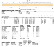
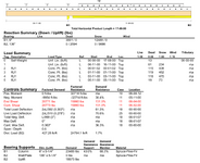
I come across the situation often enough and I want to know if I'm designing things right or if I am cheating. I use iStruct but I imagine other software is similar. When I put a beam in line with a wall with a cantilever I can only get the beam to pass if there are two bearings. I get the beam to work by creating a gap between the walls at the corner where the cantilever starts. This is usually an inch or two. For example if I had a cantilever of 2 ft extending out from the wall, the beam analysis would show 2ft unsupported, 5.5" bearing, 2" gap, 6' of bearing. Is this OK? I can't think of anything else. In reality the beam would be sitting on the very top plate and there would likely be a stud pack at the corner.
If the gap is too small, I get a shear failure on the wall bearing. If I increase the gap by an inch or two, the shear goes away. How (in real life) would I have to install the beam? Is there something else I should be doing to analyze this correctly?
In the example below, the second output that fails shows the same size bearing length on the diagram but B2 but its actually 2" longer (2" closer to B1).
Thanks,


