I'm with CANPRO et al on:
1) The shear flow theory that applies (or doesn't apply) here and;
2) the value of a correct theoretical understanding even if a gross, overkill approach would do.
I'll tell my story the the long way let folks pick and choose which bits they might light to challenge.
THE TWO COMPONENTS OF COMPOSITE FLEXURAL FASTENING
3) All components of the cross section must be induced, by the fastening, to assume the same curvature along their independent axes. This is usually the low demand aspect of fastening demand.
4) Where the joining of the components would increase the moment of inertia of the assembly above the sum of the separate components, the fastening must also axially extend and axially compress the component parts uniformly. This is usually the high demand part of the fastening demand as outright elongating or shortening a piece of steel really takes some doing.
THE SPECIAL CASE OF ALL COMPONENT NEUTRAL AXES BEING COINCIDENT
When this is the case, #4 is unnecessary and #3 is all that applies with respect to the fastening. This should make intuitive sense because, really, if your moment of inertia isn't going to get pushed any higher than SUM(Ix_components), why should you have to pump a ton of capacity into making that happen? You shouldn't, of course.
HOW TO FASTEN WHEN THE COMPONENT CENTROIDS ARE COINCIDENT?
It doesn't take much really. And there are two options. In step by step fashion:
1) Based on the ratio Ix_component / Ix_assembly, figure out how much load goes into each competent part. This will create a condition wherein all component parts have the same centroidal curvatures along their lengths and share a common cross section strain profile (this last bit is really what the crux of composite flexural action is).
2) Having determined the load on each component, the shear and moment diagrams for those components become determinate. They are what they are and they need to be internally consistent.
3) The problem now becomes one of imposing the requisite shear and moment diagrams from #2 on the component being fastened given that it may be that no external load is applied to the component. There are two fundamental approaches:
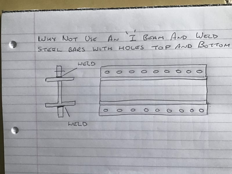
a) Transfer increments of shear from the assembly to the component to replicate the shear diagram that the component should have. This will result in the desired moment diagram falling into place. In this case, the welds would be designed for vertical loads only of a magnitude equal to the distributed load going to the component divided by two, applied top and bottom. This is often how we do it in wood and the fastening demand is very light except, sometimes, at reaction points, cutoffs etc where large amounts of concentrated load must be moved in or out of the component locally.
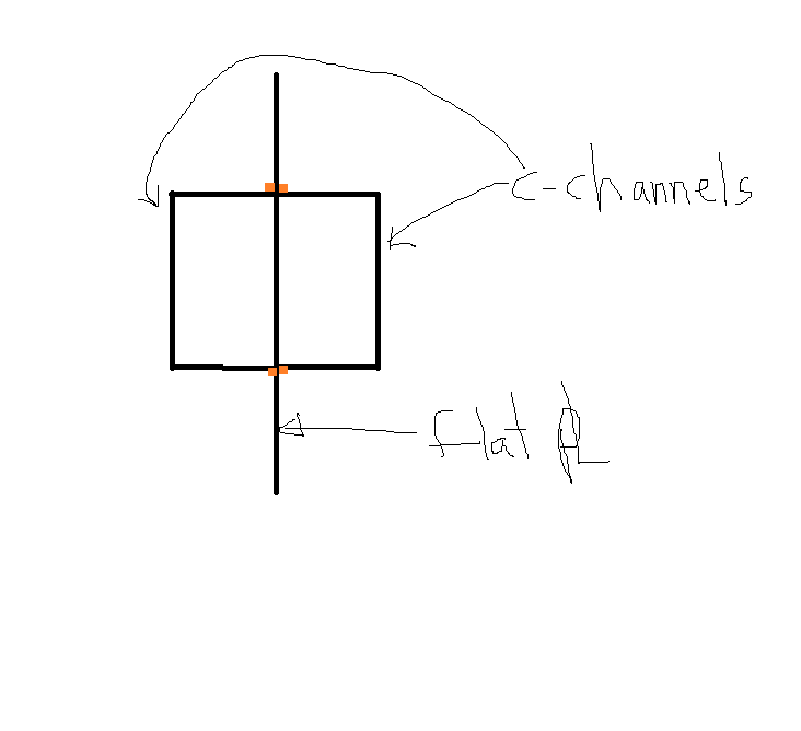
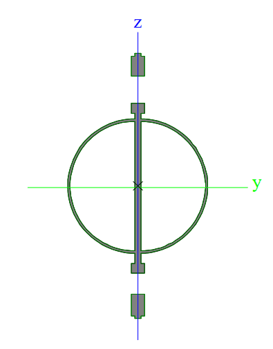
b) Transfer increments of moment from the assembly to the component to component to replicate the moment diagram that the component should have. This will result in the desired shear diagram falling into place. In this case, the top and bottom weld lines would be designed for horizontal loads only of a magnitude equal to [V/h], varying along the length of the beam [V = shear; h = distance between weld lines]. This is the method that I would favor for this application given that the path for vertical shear transfer is made a bit flexible as a result of it needing to pass through the channel flanges and induce transverse bending there.
One or the other of 3a or 3b will usually make more sense than the other based on the connection style etc. Where it's not obvious, I'll design for the worst of both cases. It's usually a pittance either way.
One could certainly be forgiven for getting the impression that #3a and #3b are both versions of "shear flow" (especially #3b). Both methods do move load around via weld shear after all. For me, the difference is that neither method attempts to impose a uniform axial strain on a component of the section which I take to be the thing that defines a classic "shear flow" problem. I suppose that another way to look at it is to say that the coincident centroids case is really just a special case of the shear flow problem in which it is possible, but not necessary, to transfer load into the component members via horizontal shear.