Blackstar123 said:
Isn't "d" the distance from the centroid of the gross section to the centroid of area consider for shear flow calculations?
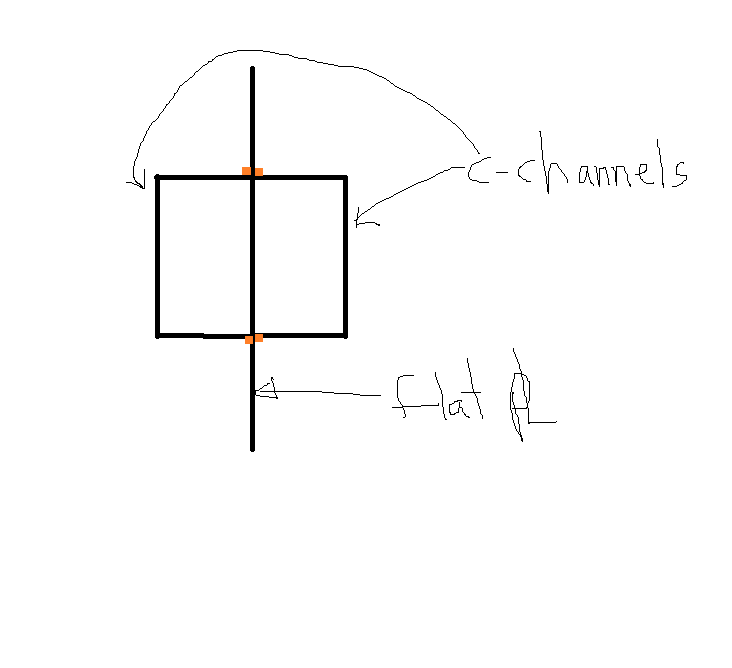
Correct, and the centroid of the area we are considering (the channel) is the aligned with the centroid of the built-up section, therefore no shear flow.
retired13 said:
I could be wrong, but isn't Q is the area above the cross section in concern, times the distance measured from centroid of the area to the neutral axis, so the maximum shear flow/stress is at the centroid of the cross section, composite or not?
My understanding is that it is the entire area of the component (the channel) multiplied by the distance from the component centroid to the centroid of the built-up section.
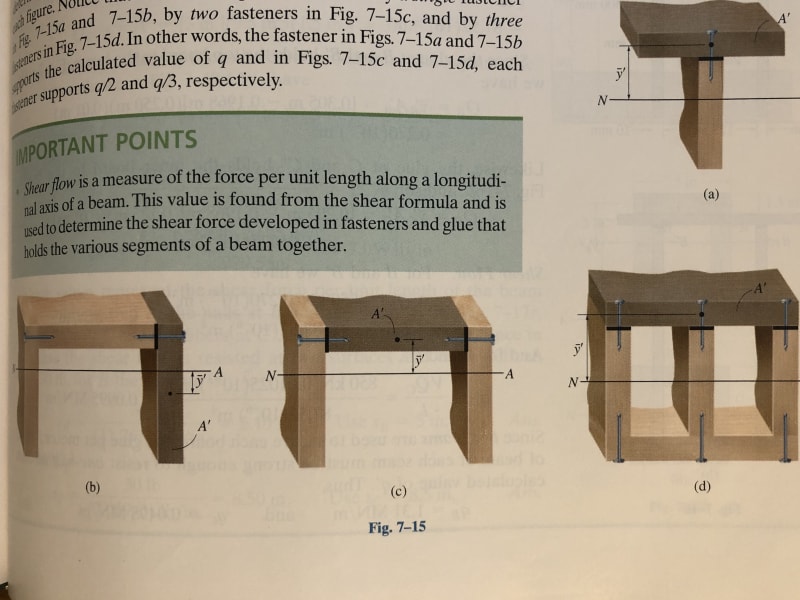
Think of the shear flow requirement in terms of how you build up your combined section properties. When determining your Ix of the combined section you first just lump together Ix for all individual components - you get to include Ix of the components just for showing up. After that, you apply the parallel axis theorem, which considers the distance from centroid of component to centroid of built-up section (a*d²) - this is where you start to get the most benefit of a built-up section (ie adding flanges to a vertical plate instead of just stacking plates together vertically). But, in order to develop this added benefit in the section (a*d²), you need to ensure the components are adequately fastened together to act as a unit (shear flow, a*d).
In this scenario, since the all of the centroids align, we only get to add our Ix values together, no added benefit from offsetting the channels, and zero shear flow.
Craig_H said:
In order to determine how much shear will flow into the channels, you need to consider the relative stiffness of the channels to the entire built up section. Take the x axis as being horizontal in your sketch, and the y axis as being vertical. Compare your Ix of the channels to the Ix of the built up beam. Stiffness attracts load, so the channels will carry that proportion of the flexural moment.
Now that you know the proportion of the applied moment being carried by the channels, determine your limit state flexural moment for the entire beam. Now, use that value to determine the flexural moment in the channels. Take this value, divide it by the depth of the channel, and voila you have the force couple required to induce the channel moment. This is the force that your weld must resist for strong-axis loading.
I respectfully disagree with this statement. I agree with your first statement regarding the channel taking load in proportion to the stiffness (channel load = Ix channel / (Ix plate + 2*Ix channel). Once you determine the percentage of the load the channel is taking, the weld simply has to deliver that proportion of load to the channel - flexural stress in the channel doesn't come into play, and this is not the same thing as shear flow. In fact, for a simply supported beam with a UDL your maximum shear flow occurs where the flexural stress is zero.
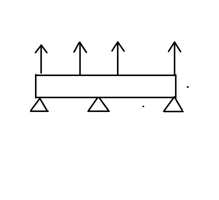
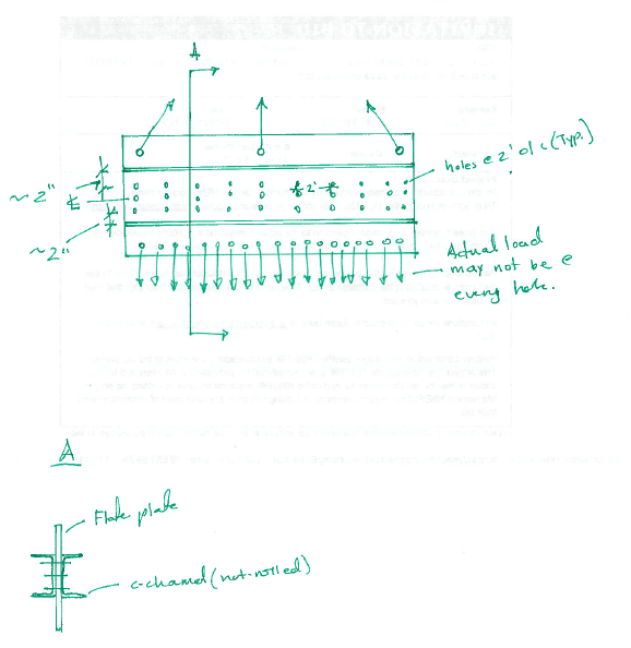
JD20, I didn't see that this is part of your other
thread. You had a nice sketch of the beam in that thread that would have been good to include here (I've included it below).
There might be (probably is) a more rational way to approach this, but I would be inclined to take 2% of the your strong axis moment, apply it as a weak axis moment, and design your welds accordingly. As Craig_H pointed out, your channels will take some of the load based on their stiffness, and that load will have to get transferred into the channel along its length and then back into the plate near the support points.