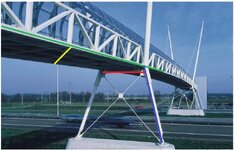
So, the load path for gravity would be: decking-stringer-floor beam. These gravity loads together with the truss self-weight would be transferred to the bottom chord and then directly to the inclined member. Isn't it?
View attachment 14851
I wounder if there are constructability issues of this setup.
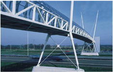
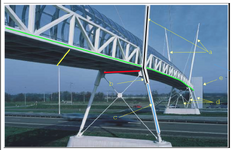
This is for the foreground support structure. Regarding the background support structure:
View attachment 14852
View attachment 14853
There are two frames in the background support structure: one with cross bracing, and the other with V-bracing. Is it aesthetically or structurally required? How would the gravity load be transferred from the bottom chord to the support structure? Is it transferred directly from the bottom chord to the support structure? If so, there would be two points for each bottom chord to transfer the gravity loads to the support structure: one on the frame with cross bracing, and the other with V-bracing. Isn't it?