Tek-Tips is the largest IT community on the Internet today!

Members share and learn making Tek-Tips Forums the best source of peer-reviewed technical information on the Internet!

  • Congratulations cowski on being selected by the Eng-Tips community for having the most helpful posts in the forums last week. Way to Go!

Truss Top Chord Lateral Support 1

hoshang

Civil/Environmental
Joined
Jul 18, 2012
Messages
507
Location
IQ
Hi all,
For a Pratt truss, lateral support is provided by a transverse U-frame consisting of the floor beam and truss verticals. What about a Warren truss? It doesn't have verticals.
 
BAretired said:
The cross braced members would be considered tension only as they appear slender enough to buckle under a compression load.
Can cross brace members be ignored in gravity load analysis if they were to be considered as tension only? If so, the support structure in the foreground would seem like the attached image, isn't it?
 

Attachments

  • Support structure model.png
    Support structure model.png
    41 KB · Views: 12
  • Truss reactions.jpg
    Truss reactions.jpg
    52.8 KB · Views: 9
X-brace members have zero stress under gravity load, but they cannot be ignored because they are required for stability of the structure (actually only one member is required for stability, but it would have to be capable of resisting both tension and compression).

Under wind load from the left, the solid red member would be in tension. The dashed red member would be in tension for wind from the right.

1751224702024.png
 
BA,
appreciate your valuable insights. Please find the attached image:

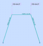
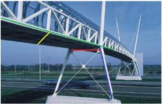
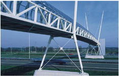
Assume the cables and its supports don't exist, the truss is supported by the inclined member (blue) via bottom chord (green). Why is the horizontal member (red) is there? Can't floor beams (yellow) between the blue lines take the same role as the red one (i.e., make yellow and red as one member? Why the red line is lower than the yellow one? is it to make a room for welding? The inclined member (blue) isn't in the plane of the truss, how the joint connecting green, blue, truss diagonal can be analyzed and designed?
 

Attachments

  • Footbridge-structural discussion.jpg
    Footbridge-structural discussion.jpg
    78 KB · Views: 7
  • Footbridge-1.png
    Footbridge-1.png
    554 KB · Views: 8
Last edited:
BA,
appreciate your valuable insights. Please find the attached image:

the truss is supported by the inclined member (blue) via bottom chord (green). Why is the horizontal member (red) is there?
The red member supports the green chord which does not align with the top of the blue member. The black member is decorative, not structural, and it prevents alignment of green chord and blue support. But even if they did align, I would use the red member to tie the frame together, making transport and erection much easier.
Can't floor beams (yellow) between the blue lines take the same role as the red one (i.e., make yellow and red as one member? Why the red line is lower than the yellow one? is it to make a room for welding?
The yellow beam (and others) are part of the floor framing of the bridge. It is not easy to see precisely what is going on there, but it is quite possible that the floor structure contains a horizontal truss to carry wind forces (just a guess). The yellow beam cannot "take the same role as the red one" because they are not aligned.

The inclined member (blue) isn't in the plane of the truss, how the joint connecting green, blue, truss diagonal can be analyzed and designed?
The blue member is certainly not in the plane of the truss...it's not even parallel. The green bottom chord rests on the red member very close to the top of the blue member.

The top of the inclined blue member fits into the bottom of the decorative black member. Its design is quite simple...design it as a simple compression member, pinned both ends with compressive force P = slope component of the vertical bridge reaction plus the slope component of the wind reaction.

1751312713179.png
 

Part and Inventory Search

Sponsor

Back
Top