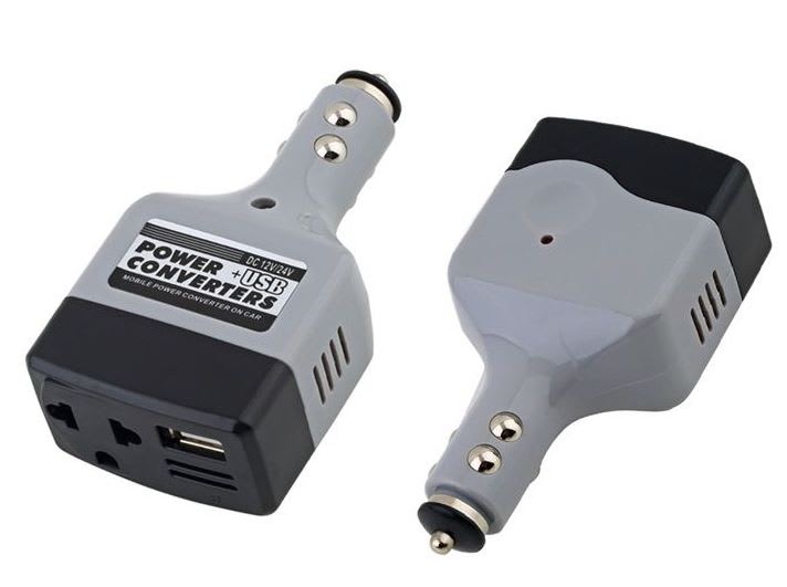
So, I've had a slight change of direction on this matter. Instead of using my old strobe light, I bought one of these from ebay. (I presumed the output would be AC but it isn't).
I have an idea, which might help anyone else who would like to learn more about this subject.
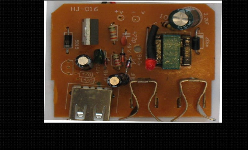
I have already pulled this device apart and taken a photograph of both sides.
I inverted the reverse side so as to give me a view as if I am looking straight through the board.
I then placed both images beside one another, so as to provide a TOP view and BOTTOM view, to make reverse engineering it a bit easier.
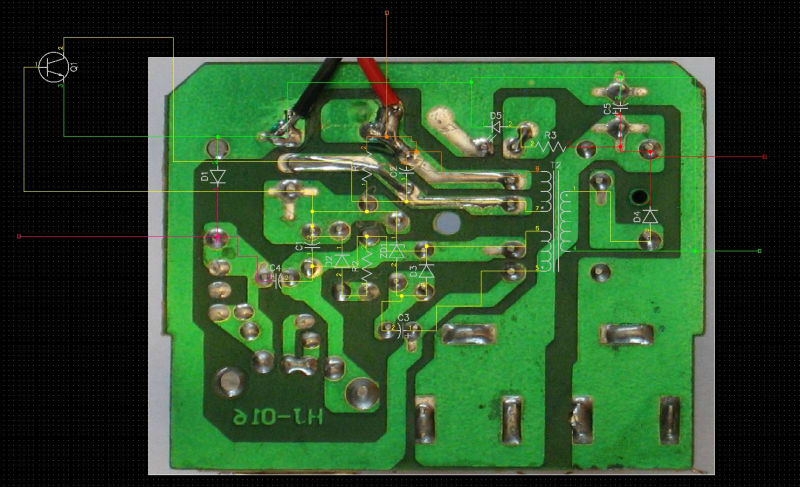
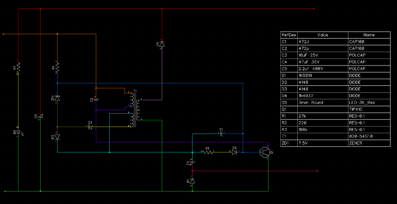
Using DIPTRACE I then superimposed the relevant components roughly in their locations, then wired it all up.
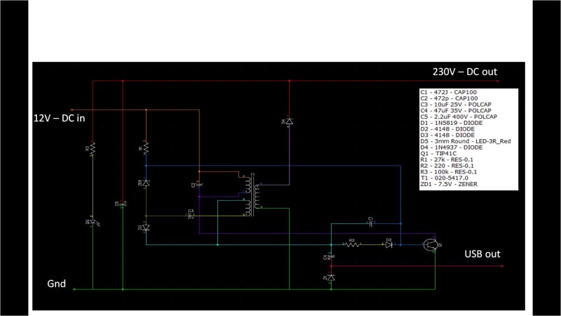
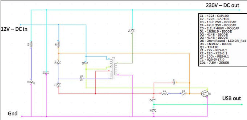
(Maybe this is a clearer image for the components names - I can't seem to make it use up the page width)
So, suppose some one of you who has a reasonable understanding of this circuit, is willing to help me along as I recreate this circuit on a breadboard, and provide a means whereby I can tweak certain components / parameters, and observe the output.
It might serve as a good reference for someone else likely to make all the cock ups I am about to make.
I purposely said that if some ONE of you, because quite honestly, I think the whole exercise would just turn into mayhem, if I was getting advice from 10 different inputs, possibly many pointing me in many different directions.
(Is it maybe even better that this would be done off line, then the final result uploaded at the end?)
The device is on ebay is only £4 so it is dead easy for someone else to easily join in and hack up one for themself, if they too are keen to use the "learn by burn" process.
The first thing I want to do, is to ditch all the parts that relate to the USB output, but to be honest, my first hurdle is understanding how this circuit works. I can understand a basic oscillator but how this Zener is positioned is confusing me. I'm pretty confident that all my components on my schematic are listed correctly, except for two items.
1. I am presuming that is a 7.5 Zener diode.
2. The transformer dots are just as was the default from the component library in Diptrace.
If anyone can spot any immediate cock ups in how I have captured the schematic can you please point it out. (Thanks).
So if anyone has any comments, and anyone feels like volunteering to be my mentor, please feel free to take the plunge!
It might all turn into a big mess pretty quickly, but I'm ready to do the donkey work, if it seems a useful exercise to any of you.
")