I am working on load rating of an existing bridge structure; a reinforced concrete arch built in 1902.
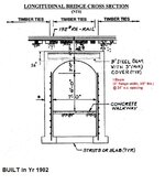
The structure has a short 7ft clear span with concrete profile, with 16” thick arch ring which encases 10” deep rolled steel beams spaced at 2ft on center spacing.
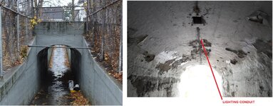
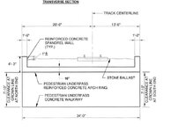
See attached sections of the bridge and representative photos.
(A). Based on the arch profile (with nominal surface reinforcement) it appears that the structure should behave like an arch and should be analyzed as an arch.
(B) However, the presence of the embedded steel beam makes me believe the original intent might be to treat it like a flexural member, so consider the steel beam as the main load carrying element and analyze as beam with fixed ends. Evaluate for the positive moment at mid-span which is WL2/24 for uniform load. The negative fixed end moment, WL2/12 will not govern since the depth of the structure at that location is significantly large (abutment walls).
Any thoughts on how the structure should be best analyzed, A or B? Would appreciate, if you could direct me to any references which would provide guidance on why a particular behavior is expected.
There were no significant cracks (only few minor hairline cracks) observed at the underside of the structure in the crown area.


