Continue to Site

Eng-Tips is the largest engineering community on the Internet

Intelligent Work Forums for Engineering Professionals

  • Congratulations waross on being selected by the Eng-Tips community for having the most helpful posts in the forums last week. Way to Go!

stresses in framed structures

chthulu

Student
May 7, 2025
12
Hi,
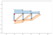
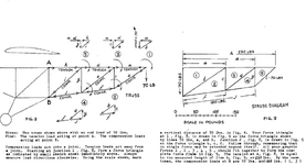
In the picture that follows, is fig 9 correct?
Using the scale in pounds shown there, the 70LBS line seems to be correct, where line a seems to be more or less 110 lbs and line b seems to be more or less 130 lbs, but using trigonometry I got something else for a and b.
So, is it possible to get a and b through trigonometry?
If you draw the line for the 70lbs according to the scale in pounds, how do you know where to stop when drawing a? or b? if you start from b.
I mean line a could be any length and fig 8 does not indicate how long line a should be.
What would be the best way to add the sketch of fig 8 together?
I really do not understand even how the 180 and 230 lbs are get.
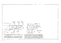
stress diagram.png
 
Replies continue below

Recommended for you

you say you made a FEM of the structure ... how did you place the nodes in the FEM ??
 
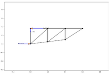
Attached is the analysis, I simply printed the fig. 8, with a ruler checked the important sides and then with the online truss calculator I generated the output.
For instance line c is 1.3 cm so in the online truss calculator that uses meters I put 0.13
Here are the two output.


Axilforcelatest).pngReactionsLatest.png
 

Attachments

  • Expenses2025-05-09 14-18-01.491046.pdf
    204.6 KB · Views: 0
ok, you used the member lengths to determine the position of the joints. so now the joints have a position in space, and so co-ordinates. So you could ask the FEM where the nodes are. But this doesn't matter.

Having drawn the last bay as you have, then you know the answer (to the lengths of each side). You could construct it by drawing the vertical line first, a horizontal line through the top point. And from fig 8 measure the inclination of the diagonal line and draw a corresponding line. This will work out like your FEM, since you measured the lengths of each line, you know the vertical line represents 70 lbs, so scale for the other members.

Then move on to joint 2 ... you already have the inclined member, drop a vertical from the far end of the inclined line, draw a line representing the lower slightly inclined member.

If you're not understanding this, maybe Will (a fellow kit builder and hobbyist) can help more than I can.
 

Attachments

  • Doc1.pdf
    51.1 KB · Views: 2
no, at the end I was not able to do it graphically, so I have done as above and save the day.
I will wait for someone to show me how is properly done graphically.
 
The diagram is, AS THE ORIGINAL TEXT states, a superposition of all the joint diagrams, and I have explained how to construct it in one of my posts. I don't teach stupid.
 
I can follow instructions, but there is no way that I can accurately copy those triangles, the angle between c and b seems to be 45 degree and I am not even sure of that (actually is between 56 and 57 so no way that I would get it right ), even worse with triangles e,c,f and i,g,J where the angles are different, event the slightest mistake will not allow you to get the results that he get in that picture, namely 230, 180 and 70 lbs. Maybe an artist or someone that has done it millions of time will be able to draw the inclination of J and f accurately, but not me, so I conclude that graphically its not for me.
The thing is not how to put triangles together, because it is shown in fig. 9, the issue is how to get the right inclination of line J and line f.
 
Last edited:
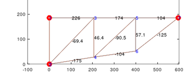
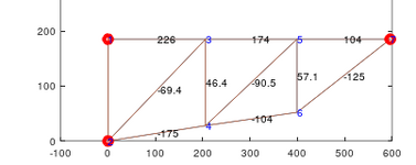
Well, if you finally get around to doing it properly you should get something like this for the bar forces. I got the geometry by cursoring figure 8
Coord=[0 185 0;0 0 0; 206 185 0;206 28 0;399 185 0;399 52 0;596 185 0]; % coordinates of nodes
Con=[1 2; 2 3; 3 1; 4 2; 3 4;3 5; 4 5; 4 6; 6 5;5 7;6 7]; %connectivity of beams
A maxwell diagram is merely the polygon of forces at each joint superimposed, as the original text and at least one subsequent post tells you.

1746838011062.png

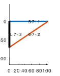
Here's the force polygon for node 7 where the 70 lb force is applied

1746839072600.png
 
yes accurately copying the structure is the problem with graphical methods like this.

ok, you say you can follow directions; the directions in your post and in my posts have been pretty clear. I think the problem is in carefully measuring the angle of the structure. Ok, why not make life easy for yourself, and make your own structure, something like the original, but with dimensions that make it easy to measure angles. Actually I think you are very close to this, with your FEM (back on past 10). The results are close to fig 9, so the dimensions are pretty accurate.

I understand you didn't input dimensions, but rather member lengths, ok fine.
point 1 is at (0,0)
point 2 (0,1)
point 3 (1,1) (but if you want to get the 230 lbs this should be closer to (1.1,1) (i get 1.095,1)
point 4 (2,1) or (2.2,1) or (2.19,1)
point 5 (3,1) or (3.3,1) or (3.285,1) these will give 210, 231, or 230
point 6 (1, 0.1) or something like
point 7 (2, 0.2)
obviously make 6 and 7 under 2 and 3
whatever dimensions, verify the member lengths (and fine tune)

now you can see the slope of the member at the RH end is 0.8/1 (or something like depending on where you place things)
so now you can work through the graphical method. You should be trying to understand the procedure, rather than getting the exactly same answers (particularly as you can analyze this a different way and confirm your answers). if you post your work here we may help out.

I think you are having trouble with basic concepts and analysis, or maybe it was just not being able to get an accurate angle. Angles aside I didn't see much in the discussion about working through the method (but it could be that in having trouble with the initial steps that you got thrown.

Do you understand a Free Body Diagram, and the equations of equilibrium (or static equilibrium) ?
 

Part and Inventory Search

Sponsor