Continue to Site

Eng-Tips is the largest engineering community on the Internet

Intelligent Work Forums for Engineering Professionals

  • Congratulations 3DDave on being selected by the Eng-Tips community for having the most helpful posts in the forums last week. Way to Go!

Single Line on Piping 1

jafary64

Mechanical
Nov 12, 2009
31
Hi, my friends,

I would like to ask about the single-line documentation on piping.

  • Is this document required for piping design?
  • What is the purpose of this document?
  • Which discipline(s)—piping, process, or others—are responsible for issuing and revising it?
Thanks a lot.
 
Replies continue below

Recommended for you

Eh?

You're going to need to describe what a "single-line documentation on piping" actually is. An example might help as well.

SO I would start with "What is this document?" And who is asking for it?

Only then can I work out what you mean, but maybe someone else knows what it is you're asking?
 
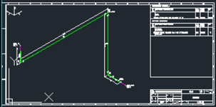
- Isometric piping drawings are not scale drawings. Single line drawing is not a standard terminology and used for dimensioned drawings and
which shows the size and location of pipes, fittings, and valves. The pipes drawn with single line regardless of the diameter.
 
Last edited:
"Single line documentation" could be anything.

P&ID, PFD, schematic, Isometric, could even be a single line diagram - which is an electrical drawing.
 
Most probability is piping isometric drawing,single-line drawing is not a professional term
1748346300592.png
 
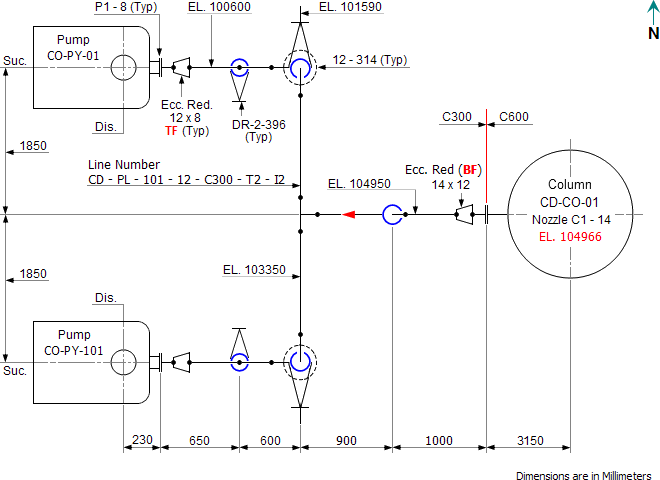
To me a piping single line is a scaled 2D plan view drawing showing the major piping runs as centerlines only. Think old school pen and paper drafting where flanges, valves, etc. are drawn but the piping is just shown as a centerline.

This is sometimes used usually early on in a FEED or study level project by piping for initial routing, rack layout, and establishing preliminary rack sizing, but is replaced with the actual orthographic ("two line") piping drawings once 3D modeling starts.
 
Let the guessing games begin !!!! .... This third-world clown will never define his terms, nor does he care if his question is answered !!

He will not provide details and refuses to give exerpted .PDF details of the document he misunderstands !!!

He just enjoys teasing the barely sentient WESTERN geezers remaining on ENG-TIPS !!!


BHAHAHAHAHAHAHAHAH !!!
 
JUST DRAW A SINGLE LINE DOWN THE CENTER OF THE PIPE


site_pa_sl.gif
 
"Single Line Drawing" is typically an electrical term for high level electrical system architecture. Perhaps you are thinking of the above orthographic drawing style where smaller bore lines are drawn with a single line for the centerline of pipe.

There are a few types of drawings that are mostly standard for piping design (not including detail sheets, etc.)
- Piping Isometrics (Primary isometric view fabrication and installation document)
- Piping Orthographics (Typically in lieu of isometrics)
- General Arrangement (lays out equipment on the side)
- Piping Location Plan (Overlays the general arrangement showing piping, calls out each line with its designation for general reference)
 

Part and Inventory Search

Sponsor