Continue to Site

Eng-Tips is the largest engineering community on the Internet

Intelligent Work Forums for Engineering Professionals

  • Congratulations waross on being selected by the Eng-Tips community for having the most helpful posts in the forums last week. Way to Go!

Shearwalls - vertical/horizontal offset combination

Status
Not open for further replies.

CEmonkee

Structural
Mar 8, 2008
111
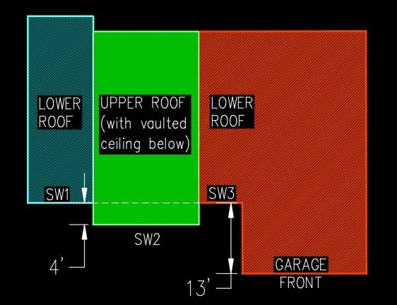
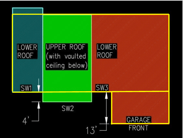
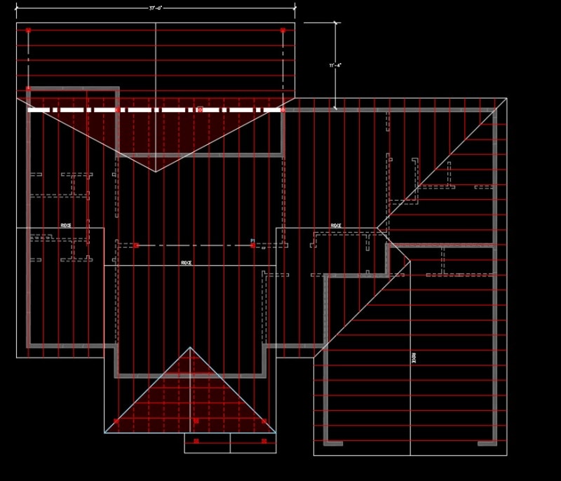
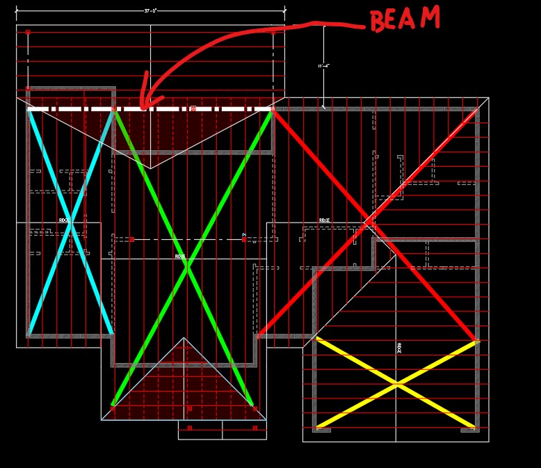
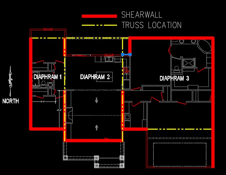
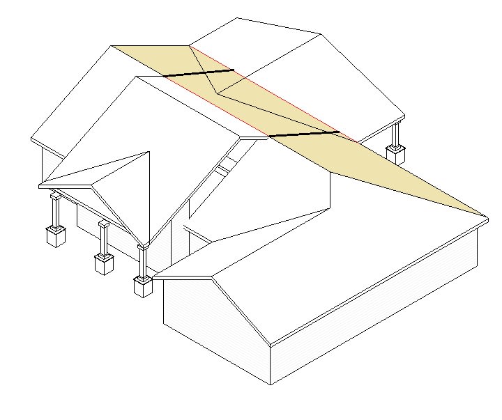
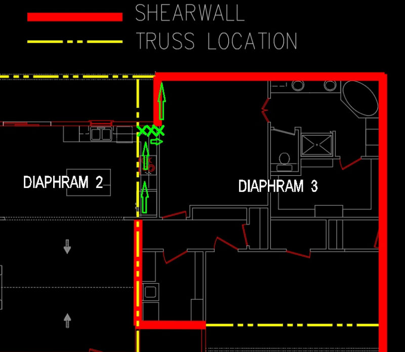
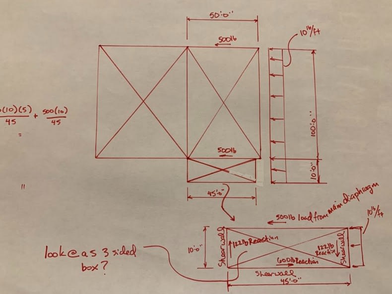
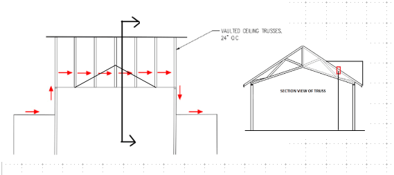
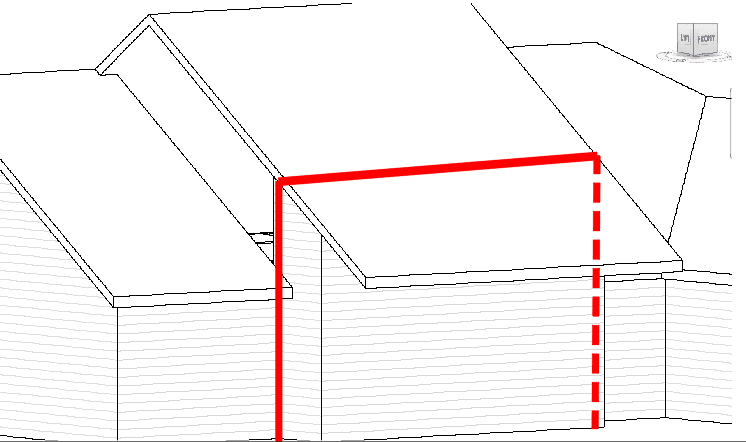
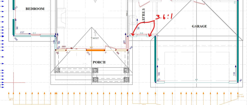
I have a question on a 1-story wood frame house that has a center section that is vertically and horizontally offset from the adjoining sides. Please see the attached figure (the image on the left is an isometric view of the house, the center image is a plan view of the roofs and shearwalls, and the image on the right is a section through the vaulted ceiling area at the shearwall line).

I need to transfer the shear from SW1 over to SW3. I've done residential structures before with horizontal offsets - this is the first one I've done that also is combined with a vertical offset. I'm trying to figure out what is the best way to detail this...

Any advice would be greatly appreciated!
 
 https://files.engineering.com/getfile.aspx?folder=aebf97f5-32a3-4e71-a715-bbb346d40101&file=shearwalls-offsets.jpg
Replies continue below

Recommended for you

Looks like the simplest solution is two columns (actually vertical beams) and a horizontal strut or tie threaded through the trusses. With wind suction, it could be in compression or tension. You might want to place a vertical member in the trusses at the right location to provide lateral support to the horizontal member.

BA
 
I've modified your elevation and truss section view. Does the sketch reflect your design correctly?

image_tknswt.png
 
Thanks for your reply BAretired. Does the sketch below depict what you're describing?

Screenshot_2020-09-24_124920_r4bj15.png


One issue - the shearwall on the right side (labeled SW3 in the image I attached in my initial post) has a window in the center and the side segments have aspect ratios of 3.6:1, so I can't use it as a segmented or perforated shearwall. I ran a calc using the Woodworks Shearwalls program and the shearwall on the left side of the vaulted ceiling has enough capacity.

woodworks-x_l4xgj3.jpg


I just started using Woodworks and I am not quite up to speed on it... I might just go back to hand calcs until I'm more comfortable with it. Just thinking, could I consider the lower roofs on the left and right side of the vaulted ceiling as a separate diaphragms... or am I over complicating this? [glasses]

Screenshot_2020-09-24_132118_cbdtrp.jpg


Thanks!
 
One issue - the shearwall on the right side (labeled SW3 in the image I attached in my initial post) has a window in the center and the side segments have aspect ratios of 3.6:1, so I can't use it as a segmented or perforated shearwall.

Can't you just add post on each side of the window, and connect the columns by beam?
 
Hi retired13,

I suppose I could do that. What do you think of breaking it into 3 separate diaphragms?
 
I think it is the way to go. You are essentially simplifying the issue rather than make it more complicate.
 
This is what I've in mind, if feasible.

image_dcmxxp.png
 
Here is the full outline of the building with more detail...

Screenshot_2020-09-24_150652_pvcgdt.jpg


I'm thinking it would be easier to break it up as shown below...

Screenshot_2020-09-24_151611_sfqqtt.jpg
 
As long as there is no discontinuity in the load path, I think it will work.
 
Okay, I think I'll start with that. I may have some more questions once I get further into the analysis. Thanks for your input so far, I really appreciate it!
 
You are welcome. The discussion helps. Good luck.
 
I now have a better idea of how the roof will be framed. Below is a plan view of the house – the thick red lines are possible shearwall locations, the yellow dashed lines are where trusses are located that I plan to use as drag struts.

plan-view_ixlslh.jpg


As I noted previously, the roof in the front of the house is vertically offset at the center section. At the back side of the house beyond lower roofs’ ridge lines, the roof is all in the same plane (gold area outlined below).

iso_aaciks.jpg


A couple of questions:
1) On the back side of the roof, I was going to specify boundary nailing along the diaphragm edges as indicated with the thick black lines. I am a little bit uncertain about how the diaphragm will behave – in the front of the house it is three separate diaphragms (due to the vertically offset roof), but it is one plane at the back. Loading in the north/south direction (front to back) seems straight-forward, but how will the diaphragms behave in the east/west direction? It seems like Diaphragm 2 will be very minimally loaded (for wind loads), and Diaphragms 1 and 3 will take the majority of the loading, depending on the direction of the wind.

2) At the boundary between Diaphragm 2 and 3, I would like to transfer the force over to the shearwall as shown - there is about a 2.5 ft offset between the drag strut (truss) and shearwall. What is a good way to do that? There is another truss directly over that shearwall…

blocking_kyywqo.jpg
 
I'm rethinking how I am breaking the diaphragms up...

I found this thread today:

thread507-462591

It gave me the idea of taking out the strut force between the two walls on either side of the center roof and distributing it to the two perpendicular walls (as was discussed in the thread I referenced above):

Screenshot_2020-10-11_140016_zik5se.jpg


If anyone has some time to take a look at this, I would really appreciate it - thanks!
 
Status
Not open for further replies.

Part and Inventory Search

Sponsor