Tek-Tips is the largest IT community on the Internet today!

Members share and learn making Tek-Tips Forums the best source of peer-reviewed technical information on the Internet!

  • Congratulations JAE on being selected by the Eng-Tips community for having the most helpful posts in the forums last week. Way to Go!

Odd Vertical Bracing 1

Nick6781

Structural
Joined
May 15, 2024
Messages
47
Location
CA
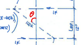
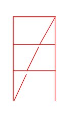
The vertical bracing layout should follow the configuration shown in the snippet below. Since the compression force is continuous through the bracing members, gusset plates, and beam webs, I believe I need to verify whether the weak-axis stiffness of the beam is sufficient to brace the bracing member per Appendix 6. I'll also need to check beam shear.

Am I missing any other critical checks?
1750705479230.png
 
Thanks for the elaboration CDLD. I agree that for most beams mode 2 would be more critical though I can imagine a torsion ally strong memento like a HSS, mode 1 could dominate.

Regarding your calculations, it is late in the evening for me so I won't attempt to digest them. Maybe they cover it all, but they seem a little too brief. Though I would suggest that I feel like things are a little more involved than a mere torsional stiffness check. In the same way that LTB quickly gets murky in practice and the analysis is half empirical, this would be similar. Non linear effects would be significant as would incidental eccentricities.
 
Yeah you may be right.
As for the calculations being brief, I left a lot of them out and mostly just outlined the steps.
For example, calculating the largest unbraced length of the brace and web/stiffener assembly.

I checked the torsional stiffness by analyzing the flanges independently (a simplification), which could alternatively be done by checking the rotation from torsion.
Also, I left out the strength calculations, which also need to be checked for both modes.
 
In addition to what everyone else said, if the diagonal braces (and brace forces) are large compared to the floor beams, you might want to consider configuring the (large) diagonal brace as a single long member, and interrupting the (relatively wimpy) floor beams between the brace. For example, if your braces are W14x120’s and your beams are W16x26’s I would make the W14 diagonal brace a single continuous member and interrupt the W16’s at each floor to frame to diagonal W14. (This configuration usually simplifies the brace-to-beam connections, and eliminates expensive stiffeners at the brace-to-floor-beam connections.)
 
Nice discussions.

Question for CDLD, did you use TL/2GJ to calculate the rotational angle theta? Also, I think I'll need to ask for double angles for the beam's ends to increase the torsional stiffness of the connections.

1750867315834.png
You can apply fictional loads in opposite directions to the flanges of the bracing beam (in other words torsion) and calculate the amount of beam rotation.
With the beam rotation you can determine how much the top and bottom flanges translate laterally, in other words the stiffness.
 
I didn't calculate the rotation angle theta.
I calculated the lateral deflection of the flange by using a 1 kip load and moment of Inertia equal to Iy/2 (moment of inertia of the flange).
In fact, I didn't calculate anything, these were arbitrary numbers to illustrate the steps.

If you want to go the more detailed route and calculate the rotation angle, you can refer to AISC DG 9.
I believe you will get slightly better stiffness values this way.
Not sure off hand if that formula is correct or not.


There is a spreadsheet on Steel Tools, called Torsional Analysis of Steel Members, which will provide the calculations for you.
 
I'm not entirely sure if that approach is valid, but I also couldn't find anything in the code that addresses Mode 2 directly.

We all seem to be in agreement regarding your mode 1 so I'll leave that be. As @CDLD intimated, mode 1 resistance probably needs to be a pre-condition of the other modes further down the hierarchy of instability.

Regarding mode 2, I see that as being one or the other of these (or a combination of both if one wants to get that fancy):

1) The diagonal braces doing the torsional bracing of the beam as roll beams.

2) The beam torsional capacity being the thing that braces the beam torsionally.

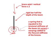
I think that one could boil this down reasonably to a rigid bar & spring check that is common in the first few chapters of many texts on stability. My quick and dirty (and probably incorrect) on this is shown below. Given the situation, I would of course add some fat to that somehow.

Obviously, "rigid bar" should be setting of all manner of alarm bells to the tune of "maybe a stiffener here".

c01.JPG
 

Part and Inventory Search

Sponsor

Back
Top