Tek-Tips is the largest IT community on the Internet today!

Members share and learn making Tek-Tips Forums the best source of peer-reviewed technical information on the Internet!

  • Congratulations JAE on being selected by the Eng-Tips community for having the most helpful posts in the forums last week. Way to Go!

Odd Vertical Bracing 1

Nick6781

Structural
Joined
May 15, 2024
Messages
47
Location
CA
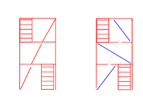
The vertical bracing layout should follow the configuration shown in the snippet below. Since the compression force is continuous through the bracing members, gusset plates, and beam webs, I believe I need to verify whether the weak-axis stiffness of the beam is sufficient to brace the bracing member per Appendix 6. I'll also need to check beam shear.

Am I missing any other critical checks?

1750705479230.png
 
That is a unique bracing layout.

I agree that you need to consider the stiffness of the weak axis of the beams. Are there other beams running in and out of the page that frame into those beams, or a diaphragm? I'd recommend having stiff plates at each connection to strengthen the beam web, regardless of whether they are required or not.
 
If resisting seismic loading in SDC D or above, I think this would be difficult using prescriptive design per AISC.
Do the beams in your diagram represent floor levels ?
The type and ductility of this frame needs to be addressed if SDC D or above. That is a pretty significant hurdle.
 
I am not following the connectivity.
  1. Is the brace centerline and beam centerline the same location or offset?
  2. Are the beams also serving as floor beams?
  3. Fixed or pinned connections?
  4. Appendix 6 of what code and what year?
 
It's an open structure. The section shown is the central stair tower, with platforms connecting to the top level of the tower.

There are no intermediate diaphragms, as most of the load originates at the top level and can be transferred directly to the vertical framing through the diaphragm located there.

According to AISC 360 Appendix 6, the beam’s weak axis provides sufficient stiffness to brace the compression bracing. Therefore, using “l” as the effective compression length is justified, rather than using the full diagonal length of the rectangular bay. Does any code require the working point of a brace to be braced by a perpendicular element? If so, I can add some infill beams as shown in blue.

The structure is located in Seismic Design Category (SDC) C.

1750708164153.png
 
Does any code require the working point of a brace to be braced by a perpendicular element? If so, I can add some infill beams as shown in blue.

No code requirement for low seismic that I know of. That said, the infill beams feel pretty good if they are, themselves, laterally restrained by diaphragms. Perhaps less work for you than mathing out the solution without the infill beams.

Two stability aspects need special attention here:

1) The lateral bracing of the diagonal bracing as you suggested.

2) Roll over bracing of the beam when it's getting hammered with axial from both sides by the bracing. This bracing probably gets done using some combination of;

a) The torsional capability of the beam and;

b) The OOP flexural capacity of the braces.
 
So what keeps you from doing a more conventional, concentrically braced design? By the time that you beef up the braces and beams to perform the bracing functions, I suspect that you'll have blown any $$$ saved by having shorter brace members several times over. If connection complexity is the concern, just make them slightly eccentric, as shown below. It won't make much of a difference to anything in SDC C.

The old adage usually holds true: there's a reason everybody always does it that way. But, then, maybe you have your own reasons that we are not yet privy to.

c01.JPG
 
Thanks, everyone, for your input.

I'm not usually one for unconventional ideas—at least not when it comes to engineering—but the reason I'm proposing this is due to the stair access layout. It's something like this:


1750714034772.png

The alternative scheme (shown in blue) is another option, but it doesn't attract as much lateral shear.
 

Attachments

  • 1750713794219.png
    1750713794219.png
    19 KB · Views: 3
The alternative scheme (shown in blue) is another option, but it doesn't attract as much lateral shear.
What do you mean by "attract as much lateral shear"? Is there another stiffer brace system elsewhere in the structure?

Are the stair stringers isolated from the beams in terms of taking load?
 
I use that type of bracing quite regularly. For access for equipment or personnel.

If there is any in plane bracing members even if there isn't a diaphragm you should be ok.

But if axial loads are high and you lack much or any mid-span lateral and torsional restraint on you beams then the failure modes become quite complex and not really within the realms of 'normal' checks. KootK highlighted this well.

Two stability aspects need special attention here:

1) The lateral bracing of the diagonal bracing as you suggested.

2) Roll over bracing of the beam when it's getting hammered with axial from both sides by the bracing. This bracing probably gets done using some combination of;

a) The torsional capability of the beam and;

b) The OOP flexural capacity of the braces.
 
According to AISC 360 Appendix 6, the beam’s weak axis provides sufficient stiffness to brace the compression bracing. Therefore, using “l” as the effective compression length is justified, rather than using the full diagonal length of the rectangular bay. Does any code require the working point of a brace to be braced by a perpendicular element? If so, I can add some infill beams as shown in blue.
One thing to keep in mind is that using a shorter Lbr will yield more conservative results.
You are permitted to use an effective Lbr that provides the required compression strength (this is useful when the utilization ratio in your vertical brace is low).
1750770903756.png
2) Roll over bracing of the beam when it's getting hammered with axial from both sides by the bracing. This bracing probably gets done using some combination of
I think my calcs below would be a suitable method for calculating the roll over stiffness of the beam.
One thing that's interesting is the roll over stiffness only really needs to be checked if you have vertical bracing attached to only one side of the beam (or vertical bracing work points offset from one another).

1750773130514.png
 
One thing that's interesting is the roll over stiffness only really needs to be checked if you have vertical bracing attached to only one side...

I disagree and feel that the roll over bucking mode is present with two sided, concentric loading. Can you elaborate on your position?

c01.JPG
 
I disagree and feel that the roll over bucking mode is present with two sided, concentric loading. Can you elaborate on your position?
Let's discuss CDLD's calculations. Please see below and let me know if I’ve understood your position correctly.


1750803883228.png

Mode 2 can be influenced by the weak links at the gusset connections above and below. It's also likely that these gussets will not align perfectly, which would introduce real torsion into the beam.

As human909 mentioned, the failure modes can get more complex if I don't have an infill beam to brace the beam that is going in and out of the plan.

But if axial loads are high and you lack much or any mid-span lateral and torsional restraint on you beams then the failure modes become quite complex and not really within the realms of 'normal' checks. KootK highlighted this well.

It seems to me that CDLD was trying to derive the required torsional stiffness using the code provided translational stiffness. I'm not entirely sure if that approach is valid, but I also couldn't find anything in the code that addresses Mode 2 directly.
 
I disagree and feel that the roll over bucking mode is present with two sided, concentric loading. Can you elaborate on your position?

I concur too. As we all know even concentric loads become unstable, afterall that is what buckling is about both axial and LTB.

I'll also add that most bracing connections have some degree of eccentricity to them. And of course the concern isn't the strength of the member but the LTB behaviour. I don't know any standard code approach that would cater for this suitably. The beam could essentially have zero bending moment and zero axial load, yet it is still at risk of LTB due to the behaviour nicely illustrated above by Nick6781
.
Now in my experience this isn't normally a big problem for smaller structures with smaller loads. (Eg one of the proportions shown) And I haven't normally conducted explicit checks every time I've designed bracing members like this. But sometimes I and my approach has been rigorous FEA buckling analysis with a healthy amount of conservatism.

It seems to me that CDLD was trying to derive the required torsional stiffness using the code provided translational stiffness. I'm not entirely sure if that approach is valid, but I also couldn't find anything in the code that addresses Mode 2 directly.
I don't know US codes but I would be surprised if any code directly addresses mode 2.
 
Last edited:
I don't know US codes but I would be surprised if any code directly addresses mode 2.
While, I agree that this mode isn't directly accounted for in codes, I feel that it is fundamentally the same sort of check as mode 1.
If you can provide the enough lateral stiffness to the top and bottom flanges to within code acceptable levels you are OK.

You can apply fictional loads in opposite directions to the flanges of the bracing beam (in other words torsion) and calculate the amount of beam rotation.
With the beam rotation you can determine how much the top and bottom flanges translate laterally, in other words the stiffness.
I disagree and feel that the roll over bucking mode is present with two sided, concentric loading. Can you elaborate on your position?
I agree that it is a valid failure mode for bracing on one side or on both sides. In my calcs above, I was trying to compare mode 1 vs mode 2 and thought that I had proved that mode 2 was equally as critical as mode 1, meaning that if you check mode 1 only you are OK for mode 2. That being said, I think there was an error in my calcs, and I now believe Mode 2 is actually at least twice as critical as mode 1.

Consider these revised calcs as a possible check for the rollover stiffness:

1750857386424.png
1750857466373.png

1750857741125.png
 

Part and Inventory Search

Sponsor

Back
Top