Continue to Site

Eng-Tips is the largest engineering community on the Internet

Intelligent Work Forums for Engineering Professionals

  • Congratulations 3DDave on being selected by the Eng-Tips community for having the most helpful posts in the forums last week. Way to Go!

Help Designing Masonry Wall under Vertical load and Horizontal Point loads

Scotty Boy

Structural
Mar 11, 2025
21
Hi,

I am attempting the design the following masonry wall:
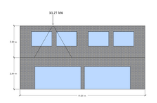
Screen shot wall.png
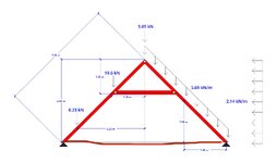
The wall is under two point loads. One is vertical as you can see in the diagram that has a magnitude of 33.27 kN. There is also another point load and it is horizontal and going into the page at the same location as the vertical point load. This has a magnitude of 30.74 kN. The forces are the result of a roof truss that has a pinned support. Hence, there is a vertical and horizontal reaction on the wall.

I am okay with designing the wall for the vertical load, but I don't know much about masonry under horizontal loads, especially point loads. So, I am wondering if someone could give me some direction on how I design the wall due to the horizontal point load at the top?

Many thanks!
 
Replies continue below

Recommended for you

We all seem to be talking past each other.

OP, forget the “truss” for a moment. Zoom out to the whole structure. It looks like you’re considering wind. Good. Think about how that wind load gets down to the foundation. The lateral system takes care of that. Do you know whether that lateral system comprises 1) shear walls, 2) braced frames, 3) moment frames, or 4) cantilevered columns? Hint: in none of these scenarios does the “truss” impart a horizontal point load into your masonry wall. If you don’t know, then it’s time to have someone else handle this, because the wind has to be taken care of somehow. Potential thrust from gravity etc. is a piece of cake after you’ve figured lateral out.

I’ll lastly point out that you probably have prescriptive provisions to lean on in your jurisdiction, given that this is apparently a residence.
 
We all seem to be talking past each other.
Potential thrust from gravity etc. is a piece of cake after you’ve figured lateral out.
I disagree. Thrust from gravity seems like the bigger picture here based on the OP's original post.
 
We all seem to be talking past each other.

OP, forget the “truss” for a moment. Zoom out to the whole structure. It looks like you’re considering wind. Good. Think about how that wind load gets down to the foundation. The lateral system takes care of that. Do you know whether that lateral system comprises 1) shear walls, 2) braced frames, 3) moment frames, or 4) cantilevered columns? Hint: in none of these scenarios does the “truss” impart a horizontal point load into your masonry wall. If you don’t know, then it’s time to have someone else handle this, because the wind has to be taken care of somehow. Potential thrust from gravity etc. is a piece of cake after you’ve figured lateral out.

I’ll lastly point out that you probably have prescriptive provisions to lean on in your jurisdiction, given that this is apparently a residence.
Hi ANE91, the lateral system is comprised of shear walls.
 
Hi ANE91, the lateral system is comprised of shear walls.
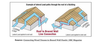
Great. Then wind goes into the diaphragm and out through the shear walls (sidewalls) and not the leeward masonry wall. Next we contend with the windward wall.
1748523281955.png
Now consider if the thing is really a truss. Tell me, are there ceiling joists that run across the bottom and connect the ends together?
 
If there's going to be a floor under the bedroom (sure hope so), then you have a bottom chord! Drop the heavy timber stuff, switch to light frame, and you'll get away from all these large loads. Include the 'floor' framing as part of a triangulated rafter system and this will all become very straightforward.

And no, you can't spread load through an opening. The masonry load spread diagram you found is right, but it assumes a solid wall. Any spread you get will be negated by the fact that it all has to drop back into the little jamb between windows.

I commend your desire to keep learning, but please, for the sake of anyone who might go near this in the future, make sure the final design is completed by a competent and experienced structural engineer.
 
If there's going to be a floor under the bedroom (sure hope so), then you have a bottom chord! Drop the heavy timber stuff, switch to light frame, and you'll get away from all these large loads. Include the 'floor' framing as part of a triangulated rafter system and this will all become very straightforward.

This...
 
Hi,

I am attempting the design the following masonry wall:

View attachment 10051
The wall is under two point loads. One is vertical as you can see in the diagram that has a magnitude of 33.27 kN. There is also another point load and it is horizontal and going into the page at the same location as the vertical point load. This has a magnitude of 30.74 kN. The forces are the result of a roof truss that has a pinned support. Hence, there is a vertical and horizontal reaction on the wall.

I am okay with designing the wall for the vertical load, but I don't know much about masonry under horizontal loads, especially point loads. So, I am wondering if someone could give me some direction on how I design the wall due to the horizontal point load at the top?

Many thanks!
Its no more simple vertical load rather there will be two components, one causing downward compression and the other causing bending in the wall. So, you have to calculate the eccentricity and compare the demand strength with the available strength. You can get the using Fs/fs+Fb/fb<1, where Fs, Fb are the stress demand for shear and bending where as the fs, fb are the available strength in shear and bending.
 
If there's going to be a floor under the bedroom (sure hope so), then you have a bottom chord! Drop the heavy timber stuff, switch to light frame, and you'll get away from all these large loads. Include the 'floor' framing as part of a triangulated rafter system and this will all become very straightforward.

And no, you can't spread load through an opening. The masonry load spread diagram you found is right, but it assumes a solid wall. Any spread you get will be negated by the fact that it all has to drop back into the little jamb between windows.

I commend your desire to keep learning, but please, for the sake of anyone who might go near this in the future, make sure the final design is completed by a competent and experienced structural engineer.
pham catching downvotes for this 😂 😂
 
If that is a room above, you have a floor that could serve as a bottom chord. How is the floor framed?

Is this going to be a real structure you are working on? You say it is a "hypothetical structure". If this will get built, you need to some direct supervision.
 
If there's going to be a floor under the bedroom (sure hope so), then you have a bottom chord! Drop the heavy timber stuff, switch to light frame, and you'll get away from all these large loads. Include the 'floor' framing as part of a triangulated rafter system and this will all become very straightforward.

And no, you can't spread load through an opening. The masonry load spread diagram you found is right, but it assumes a solid wall. Any spread you get will be negated by the fact that it all has to drop back into the little jamb between windows.

I commend your desire to keep learning, but please, for the sake of anyone who might go near this in the future, make sure the final design is completed by a competent and experienced structural engineer.

Ehh, the diagram had openings in it. And if you're going to be rude I'd rather you didn't bother saying anything. Read the thread. I said this was hypothetical.
 
Last edited:
Its no more simple vertical load rather there will be two components, one causing downward compression and the other causing bending in the wall. So, you have to calculate the eccentricity and compare the demand strength with the available strength. You can get the using Fs/fs+Fb/fb<1, where Fs, Fb are the stress demand for shear and bending where as the fs, fb are the available strength in shear and bending.
Exactly why I posted the thread in the first place!!
 
Last edited:
I'm not talking about a diaphragm. I'm talking about rafter ties. Two very different things.

And if you think a compliment accompanied by an admonition is rude...good luck.
 
Great. Then wind goes into the diaphragm and out through the shear walls (sidewalls) and not the leeward masonry wall. Next we contend with the windward wall.
View attachment 10135
Now consider if the thing is really a truss. Tell me, are there ceiling joists that run across the bottom and connect the ends together?
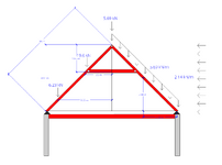
Yes, there are ceiling joists than run across the bottom. At first, however, I pictured them to be connected to the walls not the supports. Like this:Screenshot 2025-05-29 185537.png

Of course I know now that this is a poor design.
 
Last edited:
I'm not talking about a diaphragm. I'm talking about rafter ties. Two very different things.

And if you think a compliment accompanied by an admonition is rude...good luck.
You and your pal seemed to think it was hilarious.

And I was talking about the masonry load diagram.
 

Part and Inventory Search

Sponsor