Continue to Site

Eng-Tips is the largest engineering community on the Internet

Intelligent Work Forums for Engineering Professionals

  • Congratulations Ron247 on being selected by the Eng-Tips community for having the most helpful posts in the forums last week. Way to Go!

Rotational Stiffness of a Joint How to Check

Struct123ure

Structural
May 16, 2023
54
How to calculate the Rotational Stiffness of a Joint?

Background: I have gotten myself very confused as I try to do what seemed pretty simple. I have a model consisting of 2 cantilevers fix connected and a pin-pin beam between them. The structure was failing lateral drift so I introduced a rotational spring with k=(kNm/rad). Now I want to check that the beam has the capacity for this rotation.


I have created a very simple case (3m cantilever with 50kN at the end a solid rectangular steel 50mm wide X 200mm deep section I get a kθ=33 333kNm/rad. ) for myself to try to work out how to do this check:
a) At a particular moment M=σ*Sx I would calculate the stress σ(MPa)=M(Nmm)/Sx(mm^3).

b) Calculate the strain ε at the top fiber of the section using ε=σ(MPa)/E(MPa).

c) Calculate the curvature k by dividing strain by accompany distance from Neutral Axis (NA); k(1/mm)=ε/c(mm).

d) Calculate the rotation θ by multiplying a distance 'L' over which curvature is taking place; θ(rad)=k(1/mm)*L(mm). Normally this distance 'L' is taken as the depth of a 'W' section between flanges or depth of the beam. The idea is to take a L over which the beam would be stiff. (Handbook of Structural Steel Connection Design and Details-A.R.Tamboli(3ed) "rotations (θ) are measured over a distance typically equal to the beam depth." pg. 271.)

e) Calculate the rotational stiffness kθ by dividing the moment over the rotation; kθ(kNm/rad)=M(kNm)/θ(rad).

How would I check if this joint is fully rigid or pinned, in the textbook I find Equations ki=20EI/L=666 666kNm/rad and ki=2EI/L=66 666kNm/rad. I suspect the L is supposed to be not 200mm, but why would I be anything other then the depth?
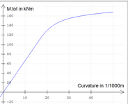
1747085460680.png
 

Attachments

  • Moment Curvature To Deflection F.pdf
    773.4 KB · Views: 7
Replies continue below

Recommended for you

Normally L refers to the span of the beam as E.I/L captures the 3 main influences on stiffness:
- Material stiffness
- Geometric properties of the section (which is where your 200mm depth is implicitly captured)
- Beam span

What it doesn't capture is the influence of connection detailing which is where you'll need to find a PhD or something
Bolt slip, steel deformation, etc will all reduce your stiffness

The normal way to do this is just to fix the beam-column end then make sure you use a very stiff connection
Fully welded is the easiest way to do this, but there are also many variations of standard solutions using bolts
Typically these bolts will be tension tightened to guarantee performance - but you'll need to think carefully about what happens if you overcome the clamping force and get some slip

I would be spending a lot less time worrying about your beam-column connection and more time worrying about your base connection
If you're doing a bolted steel connection or similar then it is far more likely that you will get rotation at the base that means you don't achieve a full base fixity
I normally put an EI/L rotational spring for columns (if trying to design for base fixity) and fully fix beam-column joints
 
Normally you don't check rotational stiffness of a joint. You detail and design it as either a rigid or pin connection. There are a range of connections that are accepted as approximation either of those conditions, even though they will not exactly provide the theoretical stiffness.
If it is two cantilever columns with a rafter between them it is easy enough to make them rigid connections which will help control lateral deflection.
Post more details if you need more help.
 
Ideastatica is a magical package and will calculate and estimate of the connection stiffness.

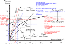
Some the classifications of pinned, semi rigid and rigid can be found here:
 
.......The structure was failing lateral drift so I introduced a rotational spring with k=(kNm/rad). Now I want to check that the beam has the capacity for this rotation.
In case of real problem, if rigid base requirements cannot be satisfied , i would prefer nominally pinned base and rigid beam - column connection .

The following doc. is the summary of too long story of rigid, semirigid and simple connections based on EC.
 

Attachments

  • GB_Structural_Modelling.pdf
    374.9 KB · Views: 10
Last edited:
It makes me feel a bit better that this is indeed more complicated then I initially assumed.
My situation is it’s steel columns with a concrete beam between. This means all the rigid connections doesn’t apply or isn’t as simple as a fillet weld.

The steel “column” is a W460x144 (W18x97) pile which is hammered into rock. I am certain that it’s a fixed connection between the column and base.

I know instead of a concrete beam I can put a steel beam and a AISC-358 prequalified connection. But I am looking for that PhD 😉.
Ultimately, I want to check the stiffness of the W460, then the stiffness of the concrete beam with reinforcement, and lastly a section taken at the face of the W460 which would be the actual connection.

But like Greenalleycat said bolt slip, steel deformation, NA shifting for the concrete beam section as it approached plasticity will complicate things. I need to get the basics down, so I made a theoretical case with a 50x200 steel section.

human909 Before I jump into any software I like to understand the process by hand. Greenalleycat I read the paper for EC.

The number 1 question I have is around L. It doesn’t make sense to me that the rotational stiffness of a joint in any ways has to do with the span of the beam?
How is the rotational capacity different if I have a 3m cantilever and I CJP weld the 50x200 vs a 6m cantilever?
1747162333056.png
 
The easiest way for me to conceptualise the influence of member's span on joint stiffness is to think about a portal frame
If you take 2 portals that are identical geometry, members, loading, etc except that one has double the beam span, what do you think will happen?
 
human909 Before I jump into any software I like to understand the process by hand. Greenalleycat I read the paper for EC.

The number 1 question I have is around L. It doesn’t make sense to me that the rotational stiffness of a joint in any ways has to do with the span of the beam?
How is the rotational capacity different if I have a 3m cantilever and I CJP weld the 50x200 vs a 6m cantilever?
View attachment 9460

You seem to be misinterpreting things. The stiffness of the joint doesn't change with member length. But the classification between rigid, semi-rigid and pinned does.
 
How is the rotational capacity different if I have a 3m cantilever and I CJP weld the 50x200 vs a 6m cantilever?

In this case , the moment distribution is a function of the relative stiffness of the member and relative stiffness of the base plate connection . I will strongly suggest you to look Hardy CROSS method ( moment distribution ) which IMO , shall be compulsory section of structural engineering text books to get the concept first.
 
Last edited:
Thank you human909 I think that's what I was missing. The joint classification stiffness shouldn't change and I guess it doesn't no matter how long the beam is, but based on the length the AISC classification would change.
 

Part and Inventory Search

Sponsor