Struct123ure
Structural
How to calculate the Rotational Stiffness of a Joint?
Background: I have gotten myself very confused as I try to do what seemed pretty simple. I have a model consisting of 2 cantilevers fix connected and a pin-pin beam between them. The structure was failing lateral drift so I introduced a rotational spring with k=(kNm/rad). Now I want to check that the beam has the capacity for this rotation.
I have created a very simple case (3m cantilever with 50kN at the end a solid rectangular steel 50mm wide X 200mm deep section I get a kθ=33 333kNm/rad. ) for myself to try to work out how to do this check:
a) At a particular moment M=σ*Sx I would calculate the stress σ(MPa)=M(Nmm)/Sx(mm^3).
b) Calculate the strain ε at the top fiber of the section using ε=σ(MPa)/E(MPa).
c) Calculate the curvature k by dividing strain by accompany distance from Neutral Axis (NA); k(1/mm)=ε/c(mm).
d) Calculate the rotation θ by multiplying a distance 'L' over which curvature is taking place; θ(rad)=k(1/mm)*L(mm). Normally this distance 'L' is taken as the depth of a 'W' section between flanges or depth of the beam. The idea is to take a L over which the beam would be stiff. (Handbook of Structural Steel Connection Design and Details-A.R.Tamboli(3ed) "rotations (θ) are measured over a distance typically equal to the beam depth." pg. 271.)
e) Calculate the rotational stiffness kθ by dividing the moment over the rotation; kθ(kNm/rad)=M(kNm)/θ(rad).
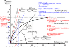
How would I check if this joint is fully rigid or pinned, in the textbook I find Equations ki=20EI/L=666 666kNm/rad and ki=2EI/L=66 666kNm/rad. I suspect the L is supposed to be not 200mm, but why would I be anything other then the depth?


