Tek-Tips is the largest IT community on the Internet today!

Members share and learn making Tek-Tips Forums the best source of peer-reviewed technical information on the Internet!

  • Congratulations cowski on being selected by the Eng-Tips community for having the most helpful posts in the forums last week. Way to Go!

RMB for width as tertiary

Viper555

Aerospace
Joined
Aug 13, 2016
Messages
13
Location
US
I'm having issues with a concept in particular that I was hoping someone could shed some light on (Y14.5-2009).

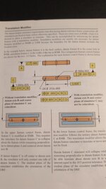
Part in question: Slender bar with hole in center of larger face (through thickness) and one hole on each side mirrored about the center hole (on same face). Larger face is primary (FS or NS not important), center hole is secondary (perpendicular to primary), and center plane of width is tertiary (position to primary and secondary). All datum reference callouts are RMB.

The example I'm looking at explains how by not using a translation modifier on tertiary, it is possible that the collapsing simulator on tertiary can cause the simulator to not grab on to both sides of the part at the same time when calling out a positional tolerance to primary, secondary, and tertiary of the mirrored holes. I believe the reasoning is that since the secondary datum takes precedence, the converging simulator only does so to the extent that the center plane it derives is coplanar with the secondary, even if only one side makes contact.

It further explains that only by using the translation modifier would you permit the total collapse of the simulator, but would result in a center plane not coplanar with datum axis B.

I can't find anything in the Y14.5-2009 standard that supports the idea that RMB does anything except collapse entirely on the part, but I'm sure it's in there somewhere. Could someone point me in the right direction? Hopefully my example is clear enough.

Thanks!
 
The standard requires datum feature simulators for datum features referenced in the same feature control frame to be basically located and oriented to each other, unless the translation modifier or a customized DRF is used *. In the 2009 version It appears in a sub-section of section 4 called "datum feature simulator requirements" or something similar. So yes, that basically means the tertiary datum width simulator must stay centered to the secondary datum hole axis. At RMB this can and probably will cause one-sided contact between the tertiary datum feature and simulator.

*Another exception they forgot to mention in that core definition is when a planar surface used as a secondary or tertiary datum feature has a location relationship to a preceding datum axis, as discussed in your other recent thread.
 
Last edited:
If all three holes are to be placed such that a plane passing through their nominal axes is nominally coincident with a plane in the center of the bar, then define the holes such that the short direction is controlled to the width of the bar and their spacing along the bar is controlled separately with a separate position tolerance to control the diametral position requirements among them however you like.

Alternatively, since the original hole is centered, just use one face of the bar.

The original case you make is that the location of the bar is to be locked in place by a fastener that expands in the center hole and some overall vice that collapses while centered on the hole to grab the outsides of the bar. In actual practice this tries to shear off the fastener if the vice is strong enough and the material doesn't deform.

If you have an example mechanism that has RFS constraint on both the hole and the width, please post a picture of it.
 
Thanks for the helpful answers! It's just an example from a workbook.
 

Attachments

  • 17511174724502599147193062863157.jpg
    17511174724502599147193062863157.jpg
    581.8 KB · Views: 49
Thanks for the helpful answers! It's just an example from a workbook.
A good educational example should start by telling about the use of the part, how it mounts and works. The selection of datum features and geometric controls should follow from that. Too many textbooks include mainly RFC examples to teach the concepts. RFC stands for Regardless Functional Considerations (a term I just made up).
 
The illustration on the left in the book does not look right to me.

It correctly shows the tertiary datum feature simulator at RMB as a pair of two parallel planes perpendicular to A and centered on B, but the planes are not at the smallest possible separation from each other. The planes should have been contracted further, which would result in a rotation of the workpiece around datum axis B in this view.
pmarc,
I assume the reason for this is the small gap visible between the upper jaw of the datum feature simulator and the left side of the actual part being inspected. Am I correct?
 
I don't know. To me, the simulator should clearly touch both surfaces of datum feature C.
 
I don't know. To me, the simulator should clearly touch both surfaces of datum feature C.
Pmarc,
Do you think the "1/3 rule" is applicable here? I mean, the datum should not be established from 1/3 of the applicable surface/datum feature or something like that (if I remember correctly).
Or maybe this 1/3 rule is applicable only to the primary datum (a rocker datum feature primary)?
 
I don't know. To me, the simulator should clearly touch both surfaces of datum feature C.
I think I'm not sure I get it. Is it because datum feature simulator B doesn't constrain rotation?

Edit: I don't think datum feature simulator C is allowed to rotate about datum axis B while contracting, if that has something to do with it.
 
Last edited:
It reminds me of:

a = "A"
b = "B"
print a/b

I don't understand why this fails when each statement is legal.

Just because something appears to be legal doesn't mean it works. Y14.5 does not guarantee that every possible combination of symbols applied to every sort of geometry results in a sensible answer.
 
After giving it some more thought, I take back what I said. The illustration in the book is correct and I was wrong. Sorry for the confusion.
 
Since the short width is not constrained relative to the central hole how on earth is one able to determine the virtual condition boundary from which the closing jaws must start in order to grab datum feature B? I am told that this distance can only be established from the initial definition for the feature, which clearly does not include the hole, yet in the textbook example the jaws might have to start considerably farther apart than the initial virtual condition boundary.
 
Since the short width is not constrained relative to the central hole how on earth is one able to determine the virtual condition boundary from which the closing jaws must start in order to grab datum feature B? I am told that this distance can only be established from the initial definition for the feature, which clearly does not include the hole, yet in the textbook example the jaws might have to start considerably farther apart than the initial virtual condition boundary.
You mean the jaws should grab datum feature C, not B. That width (datum feature C) has an MMC of 1.005 and a position tolerance of .015 RFS relative to datums A and then B, which governs the location relative to the central hole. So the Outer Boundary for it in the A,B datum reference frame is 1.005+.015 = 1.020. That is just the minimum distance the jaws must be able to spread apart to include the extreme case. But, there is no requirement that they start contracting from that exact separation.
 
You mean the jaws should grab datum feature C, not B. That width (datum feature C) has an MMC of 1.005 and a position tolerance of .015 RFS relative to datums A and then B, which governs the location relative to the central hole. So the Outer Boundary for it in the A,B datum reference frame is 1.005+.015 = 1.020. That is just the minimum distance the jaws must be able to spread apart to include the extreme case. But, there is no requirement that they start contracting from that exact separation.
Isn't the requirement stated in para. 4.11.4 in the 2009 or para. 7.11.4 in the 2018?
 
(e) Tertiary Datum Feature: Diameter or Width RMB. For both external and internal features, the tertiary datum (axis or center plane) is established in the same manner
as indicated in subpara. (d) above with an additional requirement: the theoretical cylinder or parallel planes of the datum feature simulator must be oriented and/or located to both the primary and secondary datum features’ datum feature simulators.

Then (d) states
(d) Secondary Datum Feature RMB: Diameter or Width. For both external and internal features, the secondary datum (axis or center plane) is established in the same
manner as indicated in subparas. (a) and (b) above with an additional requirement. The theoretical cylinder or parallel planes of the datum feature simulator must be oriented and/or located to the primary datum feature’s datum feature simulator. Datum feature B in Fig. 4-15 illustrates this principle for diameters, and Fig. 4-32, illustration (a), illustrates the same principle for widths.

Then fig 4-32 (a for RMB) does not have the note "No translation or rotation of datum feature is allowed".
I mean figure 4-31 (a) --also RMB case-- has the note of "no translation and no rotation allowed", but fig 4-32 (a) does not.
 
Isn't the requirement stated in para. 4.11.4 in the 2009 or para. 7.11.4 in the 2018?
I don't think so.

1000025010.jpg

Nothing in (e) either, or prior to that, indicates a simulator for a RMB width datum must initiate contraction or expansion from its OB/IB/MMB.
 
7.11.4 Datum Features Applicable RMB

When a datum feature or collection of datum features
applies RMB in a feature control frame, the true geometric
counterpart geometry originates at the MMB and
progresses proportionally through the tolerance zone
to make maximum possible contact with the datum
feature or collection of features.
Oops! Yep it's right at the beginning. But why is it important and what difference does it make if you start contracting the jaws from a separation larger than the MMB, or smaller than the MMB but still larger than the feature's Related Actual Mating Envelope?
 
Oops! Yep it's right at the beginning. But why is it important and what difference does it make if you start contracting the jaws from a separation larger than the MMB, or smaller than the MMB but still larger than the feature's Related Actual Mating Envelope?
It's important, for example, if one wants to ensure that inspection of the part is not continued when the RAME size of the datum feature is greater than its MMB size.

If it makes sense to stop inspection at this point is a whole different conversation though.
 

Part and Inventory Search

Sponsor

Back
Top