I'm having issues with a concept in particular that I was hoping someone could shed some light on (Y14.5-2009).
Part in question: Slender bar with hole in center of larger face (through thickness) and one hole on each side mirrored about the center hole (on same face). Larger face is primary (FS or NS not important), center hole is secondary (perpendicular to primary), and center plane of width is tertiary (position to primary and secondary). All datum reference callouts are RMB.
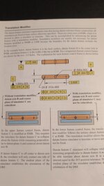
The example I'm looking at explains how by not using a translation modifier on tertiary, it is possible that the collapsing simulator on tertiary can cause the simulator to not grab on to both sides of the part at the same time when calling out a positional tolerance to primary, secondary, and tertiary of the mirrored holes. I believe the reasoning is that since the secondary datum takes precedence, the converging simulator only does so to the extent that the center plane it derives is coplanar with the secondary, even if only one side makes contact.
It further explains that only by using the translation modifier would you permit the total collapse of the simulator, but would result in a center plane not coplanar with datum axis B.
I can't find anything in the Y14.5-2009 standard that supports the idea that RMB does anything except collapse entirely on the part, but I'm sure it's in there somewhere. Could someone point me in the right direction? Hopefully my example is clear enough.
Thanks!

