I'm going to walk through this to make sure I have this right. Thanks Agent666 for posting that Portal Frame design tips.
Design procedure:
Portal Frame Design Tips Seminar Proceedings aka GEN7001 said:
Rafters
Nominal Bending Capacity Mbx in Rafters
Simplified Procedure
NZS 3404 uses a semi-empirical equation to relate the nominal bending capacity Mbx to the elastic buckling
moment Mo and the section strength Msx, which for Universal and Welded Beams and Columns can be taken as
Zexfy. This philosophy uses a set of semi-empirical equations to relate the member strength to the plastic
moment and the elastic flexural torsional buckling moment
Mbx = alpha_m * alpha_s * M_sx < M_sx
M_sx = Section strength, Z_x * F_y
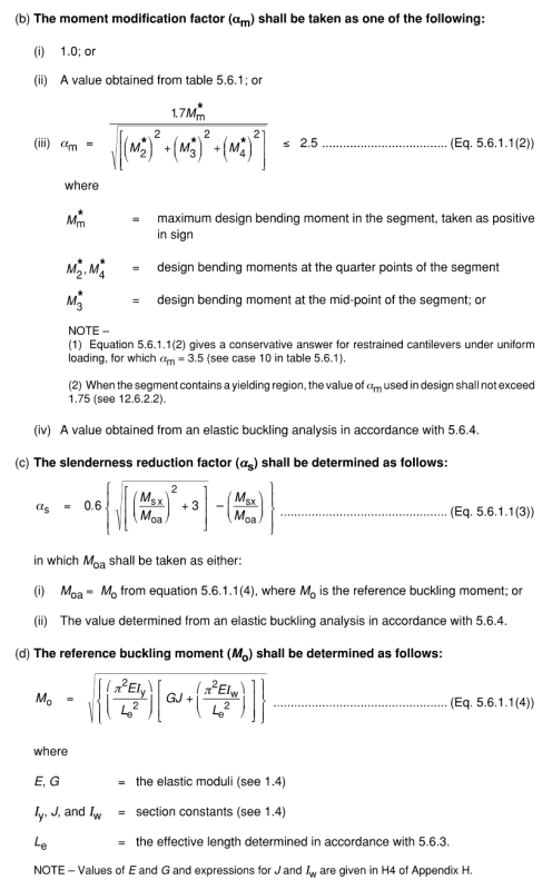
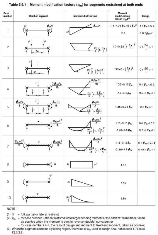
alpha_m = Moment modification factor (similar to C.b) this will increase your nominal moment capacity due to the moment distribution.
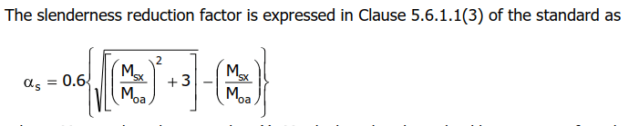
alpha_s = Slenderness reduction factor. This is a reduction factor which basically reduces your section moment strength based on the ratio of the elastic buckling strength to the section strength
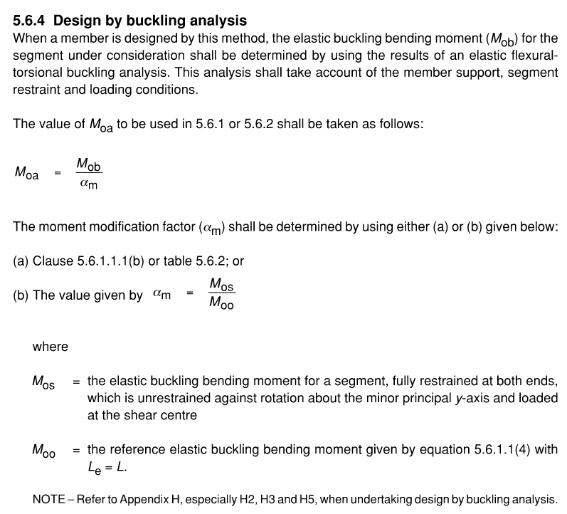
M_oa:GEN7001
So
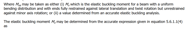
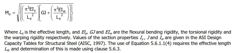
M_o:
This is the elastic buckling moment which gives almost the exact same result as AISC (calculate elastic buckling stress in AISC then multiply by the section modulus) when using the
same unbraced length
So M_o = M_oa.
This is only used to get alpha_s
Case 1: Unbraced length is full beam as it would be in AISC.
Assuming the unbraced length is long enough that LTB governs. AS4100 will give you a lower beam capacity than AISC because M.o is reduced by alpha_s. However, it seems like AS4100 says that the unbraced length is not the full length. But this gets wierder...
Case 2: Unbraced length at inflection point.
The unbraced length for AS4100 will be on the order of L/4. This will give you a much higher M_o and M.b even when multipled by alpha_s than the AISC fully unbraced beam length.
What should the unbraced length be according to AS4100?
GEN7001 said:
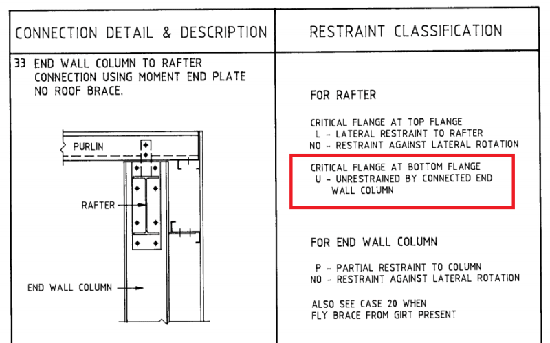
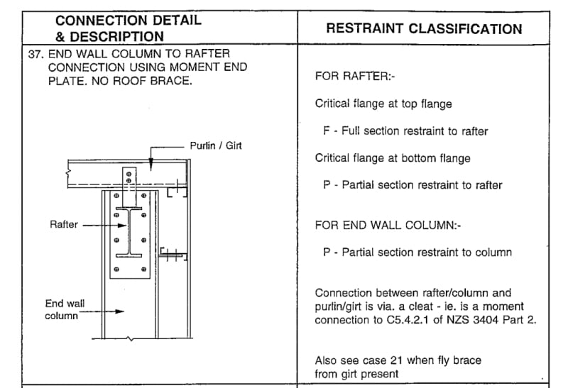
With Fly Bracing under Downward Load
The effect of the bottom flange near the columns being in compression due to gravity loads or other loading
should be considered even though most of the bottom flange of the rafter is in tension. A fly brace is
recommended near each knee and near the ridge to restrain the inside corners of the frame at kinks. A stiffener
between column flanges as indicated in Figure 4 effectively extends the bottom flange of the haunch to the
outside column flange which is restrained by girts. This effectively provides some restraint to the inside of the
knee. However, a fly brace near the knee is still recommended. With fly braces at least at the knees and the
ridge, the effective length will be 0.85 times the spacing between fly braces.
An alternative approach is to consider the rafter segment between the column and point of contraflexure if
accurately known, or nearest purlin beyond the inflection point. The inflection point is considered to be
unrestrained in determining the effective length. This approach is described in an example by Clifton,
Goodfellow and Carson (1989)
I can't seem to find this reference:
Clifton, G. C., Goodfellow, B., Carson, W., Notes Prepared for a Seminar on Economical Single Storey Design and
Construction, HERA Report R4-52, New Zealand Heavy Engineering Research Association, Manukau City, 1989
However, when looking at the bottom flange it sounds like you would take a L.e as the segment from column to the first purlin beyond the inflection point (worst case). And the end conditions of this segment are FU which gives KL = 1.0 (I think?)
Example:
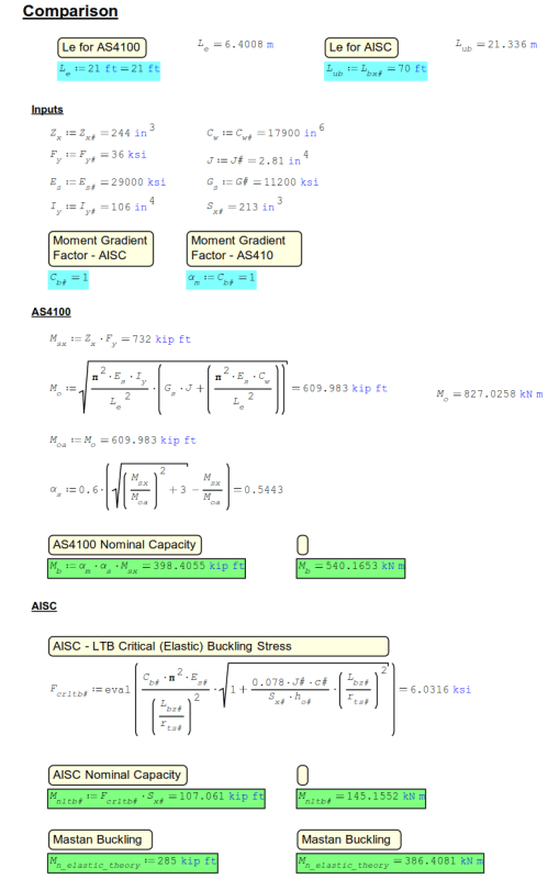
Using KootK's W27x84 70' (21.3m) long beam example. Which has lateral braces on the top flange every 7' (2.1m). Fixed in the strong axis at both ends. Point load at center causes an inflection point between the 2nd and 3rd lateral brace (on the top flange). So at about 17.5' (5.33m).
So unbraced length choices:
Unbraced Length: 70' with C.b and alpha_m = 1.0
[ul]
[li]AISC M_nLTB (nominal lateral torsional buckling strength): 107 kip*ft (145kNm)[/li]
[li]AS4100 Mo: 107.5 kip*ft, alpha_s*M_s = 95.3 kip*ft[/li]
[li]Elastic buckling strength per Mastan2: 285kip*ft (386.5 kNm). This really isn't fair to compare to the above values as I haven't factored in C.b (alpha_m),b ut this is the highest value of moment capacity that can be achieved[/li]
[/ul]
*Note - Anything above 285kip*ft (386.5kN*m) can't be achieved. The beam will buckle prior to this moment
Updated with Cb and Alpha_m
C.b = 1.92
alpha_m: 1.7
ul]
[li]AISC M_nLTB: 206 kip*ft (280 kNm)[/li]
[li]AS4100 M_b = 162 kip*ft (220 kNm) [/li]
[/ul]
AS4100_A: 17.5'
[ul]
[li]AISC: Not allowed[/li]
[li]AS4100 Mo: 839.9 kip*ft (1138.7 kN*m), alpha_s*M_s = 468.8 kip*ft (635.6 kN*m)[/li]
[/ul]
AS4100_B: 21' (brace after inflection point)
[ul]
[li]AISC: Not allowed[/li]
[li]AS4100 Mo: 610 kip*ft (827 kN*m), alpha_s*M_s = 398.4 kip*ft (540 kN*m)[/li]
[/ul]
Calc Numbers:
What is the equation for alpha_m? I can update these to include alpha_m and c.b factors.
- I will update these shortly
Side Comment: It would be great if we produced moment in Joules. Not sure why I find that so appealing. The whole energy thing I guess.
Hopefully I can get someone to double check this.
Takeaway
It seems like using the segment lengths (and please someone check these unbraced lengths for AS4100 cases) results in a beam capacity which cannot be achieved.
Edit 1: Formatting
Edit 2: Update alpha_s. This should multiply M_s not M_oa.
EIT