Alright, consider me your Mastan support staff if you need that. Or are you planning to do the Mastan yourself?
RFreund said:
Kootk - How'd you know to add nodes and apply to the load to the top of the "fake beam" and also apply restraints to the top of the "fake beam"? Just using line elements and placing everything at the centroid seems wrong, but I didn't even realize that you could take in account load height an restraint location in Mastan2
I took an experimental, evening graduate class in nonlinear structural analysis at Marquette back in 2005 with a professor who runs in the same circles as Dr. White and Dr. Ziemian. The course was awesome but would have been more aptly titled "Nifty Stuff from Dr.Z's Textook". We did a lot of Matlab etc but also spent a lot time with Mastan and worked through a lot of the precursors to what eventually became the
Stability Fun series. Of course, that was fifteen years ago now and my long term memory is crap for anything other than first principles stuff.
Using line elements placed at the centroids is just what you do, for better or worse. Some notes on the fake beams in my models:
1) All of the fake beam line elements were the same cross section as the beam itself. This was really just a matter of convenience. Mastan is not super user friendly and it's a boon just to be able to click "All Members" and apply the same cross section to everything.
2) All connections between all member segments, including the fake beam elements, were rigidly connected for both flexure and warping torsion. Again with the "All Members" business.
3) For the most part, the fake beam elements are nothing more than visual aids to allow the user to visually perceive the rotation of the beam in addition to the centroidal displacement. The one important job that they do, as you surmised, is allow you to introduce loads and restraints at locations in space other than the beam centroid.
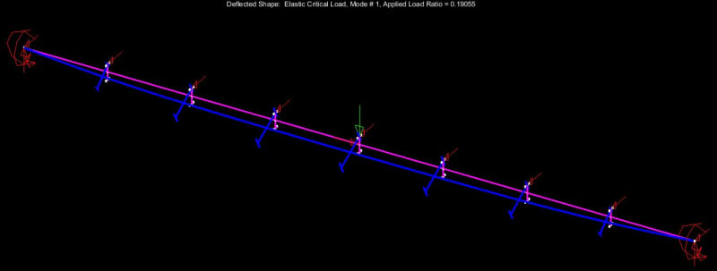
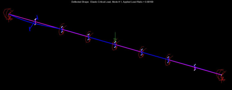
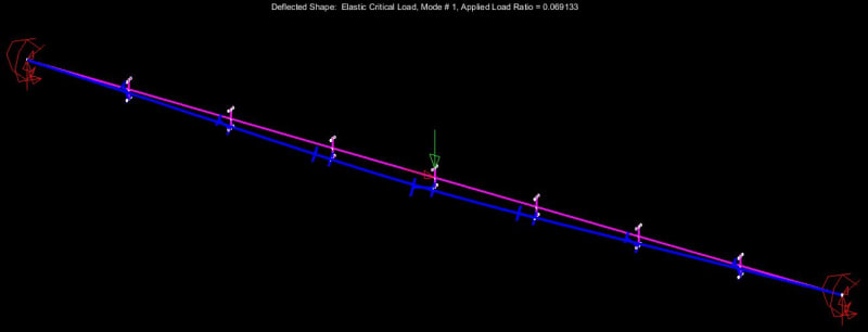
4) If you look closely as some of the Mastan output, you'll see that the presence of the fake beam elements does actually impact the results a bit. Those impacts are
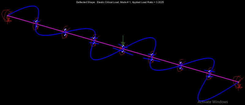
very small however and, for most intents and purposes, the fake beam elements can be considered purely "ride along", as we intend. For some of the models that I ran where the applied load ratio was in excess of 1.0, the first mode of buckling was actually the center tee stub of the fake beam twisting around ninety degrees like a goofy corkscrew. So there's that. I just put a fake x-dir restraint on the fake top flange and forced the real first mode to bubble back up to its rightful place at the surface.
5) I entertained the notion of trying to strategically chose the cross sections for the fake beams. One the one hand, you want something relatively flexible and inconsequential to minimize the impact on the overall beam behavior. On the other hand, you kind of want something stiff so that the applied loads move around with the beam rotation as you'd expect them to without any bonus flexibilities coming into play. In the end I concluded that, either way, the impact was going to be so negligible that it wasn't worth extra effort of trying to get fancy(er).
RFreund said:
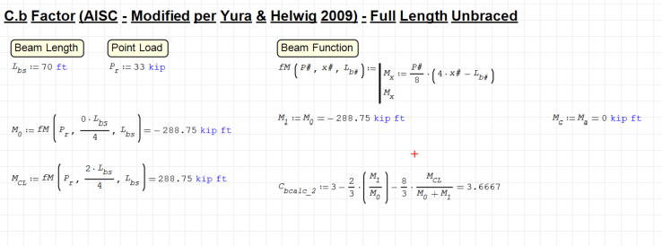
The modified equation seems to be specific to a uniform load not a point load. Maybe this is giving the error. Maybe we try to model a uniform load in Mastan2?
Sure. Do you want me to do this? Would you mind if we dropped the 70' beam example and migrated to back to the 32' test case? With the 70' case, I fear that our results will forever be tainted by "sure, but at 70' it's not a realistic example and, therefore, not wholly valid for comparison with code provisions". I actually feel that waay myself. The 70' example did it's job admirably as the hyperbolic example that it was intended to be but I think that it's time to put that one out to pasture in favor of something more representative of practical designs. Even at 32', Mastan's coming in at only 50% of the AS4100 capacity so there's still plenty of discrepancy to fret over.
How about this:
- W27x84
- 1/8 th point top flange lateral bracing.
- Uniform load producing a peak moment near the plastic moment as before.
- 32' span
- Fixed beam ends.
- Weak axis rotation unrestrained at beam ends.
If you agree to this, I'll run it as listed above and modified as follows for Cb calculation:
- Remove all intermediate restraints.
- Move all load down to the shear center.