Continue to Site

Eng-Tips is the largest engineering community on the Internet

Intelligent Work Forums for Engineering Professionals

  • Congratulations The Obturator on being selected by the Eng-Tips community for having the most helpful posts in the forums last week. Way to Go!

Position Tolerance on placed objects on a weldment 1

jamiethekiller

Mechanical
May 2, 2025
19
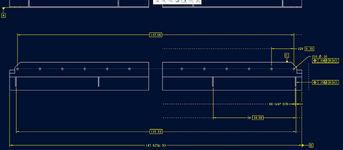
Can i use Position to locate an object on a weldment? See attached image. A is the bottom perpendicular surface.

My intent is to have all of my hole patterns and gussets symmetric to weldment centerline. I have a 5x 24 basic dimension doing the spacing of the gussets. I also added a 144" basic dimension that is overall width of the end gussets. Is that 144" dimension even needed? Does the 5x 24" dimension cover intent?

Thanks
 

Attachments

  • placed item gdt.png
    placed item gdt.png
    24.3 KB · Views: 39
Replies continue below

Recommended for you

Typically a position tolerance is applied to the centerplane or axis of a feature by identifying the width or diameter of the feature. This is indicated by either placing the requirement Feature Control Frame (aka, FCF) in line with the size/width dimension or beneath the size/width dimension. In addition, since the true position of the centerplane or axis is the basis, the dimensions should be to that centerplane/axis and not to one side or a tangency.

I would also recommend against using [B | A | C] as [B ] appears rather small. If I am guessing correctly the far face is used as datum [A]; you probably want the gusset to be perpendicular to [A] and perpendicular to [C] and then located in that orientation to [B ] so the order would be [A|C|B]

The way it is now only [B ] matters as it controls both orientations and the location to the relatively small surface making [A] and [C] redundant.

B is attached to the 147.625" dimension, which i wouldnt' consider small(over 12ft long)... B being on a FoS is giving me a centerplane to work from.

There's no datum on the far face. The bottom surface is A(the gusset is perp to that surface) and C is as shown. Its a very long and large weldment with some support gussets and 2 different hole patterns. I chose [B | A | C] because i care more about the symmetry of the gussets and hole patterns than i do the perpendiculary of the gussets and hole patterns. In the end i'm not sure the order of the datums matter on a part like this.

I don't have any dimensions coming from a side or tangency. I'm assuming i don't need a drawing axis denoting a centerplane on the drawing. Since B is on a FoS the centerplane is already defined and doesn't need to be shown? Is that correct?

I take it that i CAN just put a FCF with a leader directly to an object on a weldment and its understood(and legal)?
 

Attachments

  • Screenshot 2025-05-16 153905.png
    Screenshot 2025-05-16 153905.png
    30.8 KB · Views: 16
The far face in the view you have applied the FCF to is [A] or it is to the near face; it's the same sort of surface controlling the same degrees of freedom.

The surfaces for [B ] are small, even if the overall width isn't. If you were to clamp that in a large vice you would have a difficult time getting the part oriented as there's not much control there.

The 5 X [24.00] is to the side of the feature you are putting a position tolerance on.

It doesn't matter if it's a weldment detail or if this is machined from a solid bar - the FCF controls the location of the centerplane of the feature and is applied to either the width of the feature or with opposing arrows from opposite sides of the feature. The face is not allowed to have a position tolerance. The dimension should be to the centerplane OF THE FEATURE. The center of [B ] is assumed as is symmetry.

After the part is clamped on [B ] it can no longer have the orientation further controlled. If it goes in the vice crooked, then that's acceptable and references to [A] and [C} cannot apply; their degrees of freedom are already locked by [B ]
 
Last edited:
It doesn't matter if it's a weldment detail or if this is machined from a solid bar - the FCF controls the location of the centerplane of the feature and is applied to either the width of the feature or with opposing arrows from opposite sides of the feature. The face is not allowed to have a position tolerance. The dimension should be to the centerplane OF THE FEATURE. The center of [B ] is assumed as is symmetry.

The gusset dimension should be from center to center of gusset for the 5x 24.00 dimension?
Do i need the [144"] dimension or can that drop since the pattern of gussets is implied symmetric to B through the FCF? But the FCF can only be applied to the centerline of the gusset?

After the part is clamped on [B ] it can no longer have the orientation further controlled. If it goes in the vice crooked, then that's acceptable and references to [A] and [C} cannot apply; their degrees of freedom are already locked by [B ]
I think i understand this and it makes sense.

In practice though this isn't going to be clamped in a vise. They're going to touch off one side and then touch off the other side and establish the CL that way. We're not going to have them inspect this. I'm just using GDT as a way to deliver intent. I want the holes and gussets to be symmetric to the part. I have generous clearance on the holes that dimensioning from an edge isn't going to cause a stackup issue(say the part is .02 long and the hole pattern is offset the oposite direction .01" i can still have this part installed symmetric). Is there a better way to deliver that intent otherwise?
 
The FCF is applied to the width of the feature. The dimension is to locate the center of that feature as that is the true position of the width.

Right now all the gussets would be nominally offset to one side, if position tolerance could apply to the faces, which it doesn't.

The [144] isn't needed and some will complain that it is double dimensioning. Double dimensioning is normally a problem when directly applied tolerances are used - the claim is that features can have conflicting tolerances because of stack-up, but mainly they don't want responsibility for having to meet all the requirements at the same time by controlling features/processing. That does not apply to basic dimensions, but some complain anyway.

They aren't going to just touch off to the sides. They are going to place this on a table on [A] (if that's the top surface it may block access to put in the gussets), square it up to a stop for [C] and then, once is is aligned, they will touch off to each side to find where [B ] is.
 
Can i use Position to locate an object on a weldment? See attached image. A is the bottom perpendicular surface.

My intent is to have all of my hole patterns and gussets symmetric to weldment centerline. I have a 5x 24 basic dimension doing the spacing of the gussets. I also added a 144" basic dimension that is overall width of the end gussets. Is that 144" dimension even needed? Does the 5x 24" dimension cover intent?

Thanks
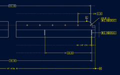
what is this gusset do?
is the flange to holes important for location?
weld distortion and shrinkage important?
are these just bolt holes for a preload?
 
The FCF is applied to the width of the feature. The dimension is to locate the center of that feature as that is the true position of the width.

Right now all the gussets would be nominally offset to one side, if position tolerance could apply to the faces, which it doesn't.

Why does the position FCF apply to the width of the gusset and not to just simply the placement of the gusset? Whether the gusset is dimensioned from a face or CL of gusset doesn't matter to me. Does it matter when placing a position tolerance on the object?

You're right about manufacturing of this. i got something twisted in my head when i was hurriedly typing my reponse. I'm nervous that if i dimension it from the side of the weldment that the gussets could in practice be off by whatever extra stock material they have left prior to machining the sides/top surface. The overall width of the weldment is going to be held within .020 but they could thoeretically have an extra inch of stock on each side. They may even have some of the hole patterns placed prior to welding and machining. So i'd much rather have everything be symmetric to the centerplane and then cut whatever is needed off the edges to ensure everything is still symmetric to FoS [-B-]
 
what is this gusset do?
is the flange to holes important for location?
weld distortion and shrinkage important?
are these just bolt holes for a preload?
The gussets are just support. its over 12ft long and need to support some overhanging load.
The one set of flagne holes bolts it to the machine. the other set of holes(helicoils) are for bolting on some other equipment to it. Its important that this large weldment can fit inside its envelope space within .06 on each side.
weld distortion and shrinkage would be dealt with in a post welding machining operation to ensure the two surfaces(not FoS B) are parallel to each other by .020.
 
(1) Why does the position FCF apply to the width of the gusset and not to just simply the placement of the gusset? (2) Whether the gusset is dimensioned from a face or CL of gusset doesn't matter to me. (3) Does it matter when placing a position tolerance on the object?

1) Because that is the rule that Y14.5 has; it is identifying exactly what it is about the controlled feature that is being placed. In the Y14.5 rules position cannot be applied to a flat surface of a feature. If you wanted that, you could use profile of surface, but that would not center the center gusset on the center of the beam with control between the centers.
2) OK, but it does matter to anyone following the Y14.5 rules
3) If it didn't matter there would not be a rule.

Is there a preferred/legal way to position the gussets symmetrically with clear intent?
 
The gussets are just support. its over 12ft long and need to support some overhanging load.
The one set of flagne holes bolts it to the machine. the other set of holes(helicoils) are for bolting on some other equipment to it. Its important that this large weldment can fit inside its envelope space within .06 on each side.
weld distortion and shrinkage would be dealt with in a post welding machining operation to ensure the two surfaces(not FoS B) are parallel to each other by .020.
Thank you for replying.
Are all 3 datums post machined?
So is it important the the holes line up for assembly. And that portion of the gusset be level. For the over hang load.
So holes to the over hang load is what is important? Is that correct
Prior to machining the holes, The machinist will have to indicate the over hang and adjust it.
Then machine datums c and d. Use for tooling.
Locate on the datums then machine the holes.
am I on track if not let me know.
So following translate that to the machinist ,
Use the appropriate ASME gd&t.
I take it datom A is where is over hang load?
Sorry I don't see all of the drawing.
I would suggest to add a parallel fcf from C to A, a fcf added to B perpendicular to A
Then leave your FCF of true position as is.
This can be debated and critiqued.
So when the machine the surfaces its all tied in.
And machined simultaneously.
 
Last edited:
The FCF is applied to the width of the feature. The dimension is to locate the center of that feature as that is the true position of the width.
 
The FCF is applied to the width of the feature. The dimension is to locate the center of that feature as that is the true position of the width.
so as i understand: There's no way to symmetrically control the locations of placed objects on a weldment that matches y14.5?
 
What part of the placed objects is being controlled?

Under Y14.5 it is the feature center plane that is controlled for features of width and the axis for circular features. The gussets are features of width and the FCF is applied to that width.

The implication for a datum feature applied to the width is to create a reference in the center of that width as a plane.

A reference to that datum feature along with any others necessary to control the orientation to establish that width set the center is used in the FCF.

If the center of the pattern of features coincides with the datum feature then no dimension to that datum feature is given and they are assumed to be coincident.
 
Thank you for replying.
Are all 3 datums post machined?
So is it important the the holes line up for assembly. And that portion of the gusset be level. For the over hang load.
So holes to the over hang load is what is important? Is that correct
Prior to machining the holes, The machinist will have to indicate the over hang and adjust it.
Then machine datums c and d. Use for tooling.
Locate on the datums then machine the holes.
am I on track if not let me know.
So following translate that to the machinist ,
Use the appropriate ASME gd&t.
I take it datom A is where is over hang load?
Sorry I don't see all of the drawing.
I would suggest to add a parallel fcf from C to A, a fcf added to B perpendicular to A
Then leave your FCF of true position as is.
This can be debated and critiqued.
So when the machine the surfaces its all tied in.
And machined simultaneously.
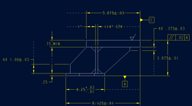
This is my profile view.

A is where its being bolted down to another piece of equipment. the parallel surface is where i'm bolting in some other items but have some adjustment ability there. Side surface of my 3/4" plate was bigger than the 1/4" plat(may or may not be 1/4" min when talking with vendor and having them machine their datum flat) so i chose that for C. I'm guessing they're going to machine that whole face regardless just so they have something flat to push up against when putting in the bolt patterns into the 3/4" thick plate.

Some of this question is just acedemic i suppose since i'm mainly focused around placing a gusset and its not very critical where its located at(hence the 1/4" position tol. Its something that comes up every so often and i'm just looking for a concrete answer or example of being able to use a FCF on placed objects to deliver intent in my design. i absolutely know that this vendor(and i'm guessing others) would strike a centerline and work off of that when placing gussets/holes and then machining the ends to be squared up to everything else.

Thanks
 

Attachments

  • Screenshot 2025-05-19 150116.png
    Screenshot 2025-05-19 150116.png
    40.3 KB · Views: 7
This is my profile view.

A is where its being bolted down to another piece of equipment. the parallel surface is where i'm bolting in some other items but have some adjustment ability there. Side surface of my 3/4" plate was bigger than the 1/4" plat(may or may not be 1/4" min when talking with vendor and having them machine their datum flat) so i chose that for C. I'm guessing they're going to machine that whole face regardless just so they have something flat to push up against when putting in the bolt patterns into the 3/4" thick plate.

Some of this question is just acedemic i suppose since i'm mainly focused around placing a gusset and its not very critical where its located at(hence the 1/4" position tol. Its something that comes up every so often and i'm just looking for a concrete answer or example of being able to use a FCF on placed objects to deliver intent in my design. i absolutely know that this vendor(and i'm guessing others) would strike a centerline and work off of that when placing gussets/holes and then machining the ends to be squared up to everything else.

Thanks
I see you had parallel,
Make datum C perpendicular to A
add an other fcf to the true position with no datum . Make the holes true position to them selfs. Composite toletance.
 
Op
I guess what I am saying is the only issue is the degrees of constraints are missing.
The datums must parallel, square and perpendicular. If I ran this job that's what I would for tooling. Square it up and use those surface
To have constant dimensions to the holes.
 
Op
I guess what I am saying is the only issue is the degrees of constraints are missing.
The datums must parallel, square and perpendicular. If I ran this job that's what I would for tooling. Square it up and use those surface
To have constant dimensions to the holes.
I get all that.

But my particular question is about the gusset location FCF and not so much the holes. The holes are straightforward. I just want to communicate the placement of the gussets to be symmetric to FoS datum B
 
Draw it so it looks symmetric and don't have any non-symmetric dimension(s)/non-symmetric datum feature reference(s).

[A|C|B] will work. So will [A|C|B(M)], if the parts of the assembly this is installed into are allowed to be wiggled relative the the long dimension.
 

Part and Inventory Search

Sponsor