Continue to Site

Eng-Tips is the largest engineering community on the Internet

Intelligent Work Forums for Engineering Professionals

  • Congratulations The Obturator on being selected by the Eng-Tips community for having the most helpful posts in the forums last week. Way to Go!

Position Tolerance on placed objects on a weldment

jamiethekiller

Mechanical
May 2, 2025
19
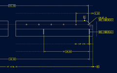
Can i use Position to locate an object on a weldment? See attached image. A is the bottom perpendicular surface.

My intent is to have all of my hole patterns and gussets symmetric to weldment centerline. I have a 5x 24 basic dimension doing the spacing of the gussets. I also added a 144" basic dimension that is overall width of the end gussets. Is that 144" dimension even needed? Does the 5x 24" dimension cover intent?

Thanks
 

Attachments

  • placed item gdt.png
    placed item gdt.png
    24.3 KB · Views: 39
Replies continue below

Recommended for you

Or alternative make the overall datum X, what ever is next. Apply two basic dimensions at each end. Add fcf true position to X at each end.
It is now symmetrical. Just make sure dimensional stack up adds up.
 
Datum feature B is too small to qualify for the primary datum feature.
 
Draw it so it looks symmetric and don't have any non-symmetric dimension(s)/non-symmetric datum feature reference(s).

[A|C|B] will work. So will [A|C|B(M)], if the parts of the assembly this is installed into are allowed to be wiggled relative the the long dimension.
i can't visualize in this on a drawing. can you give me a quick illustration?

i'm sorry if thats asking for too much.
 
Can you imagine a hole in the center of a rectangular plate? That's what looks symmetric. If there's no dimension to any edge and it looks like the hole is in the middle that's sufficient.
 
ASME removed symmetry because it was to confusing, go fiquire.
it was simple in my mind.
 
They removed the symmetry geometric characteristic variation control; symmetry remains as a base function that is handled with other means.
 
Or alternative make the overall datum X, what ever is next. Apply two basic dimensions at each end. Add fcf true position to X at each end.
It is now symmetrical. Just make sure dimensional stack up adds up.
i can't follow this in my head.

the overall width i already have set as a datum. i have a basic dimension spacing the gussets. i have a FCF of position pointing to the gusset. Should the FCF be pointing to the witness line instead of the gusset to imply symmetry to Datum B(overall width?). Do i add a centerline axis to the part? i was under the impression that is no longer allowed? Just looking to say that these gussets are symmetric to the parts overall width centerplate by 1/4" and use as little dimensions as possibel to convey that.

i'm really struggling with some of these replies unfortunately. i'm not looking for someone to do my job, but an example of what i'm talking about would be pretty beneficial.

I have some other large weldments that are just channels or i-beams welded together. In those situations i could have warpage of the beams/channels by 1/4" or more. i truly don't care about the envelope size of some of these things and there won't be any machining passes. i'd rather dimension some of the placed objects on those big frames to be symmetric to the overall width and not come off potential bad datums.

Thanks again for all the replies. i have learned some things
Here is the old standard now obsolete. It might explain it better. Symmetry has been replaced with true position. But according to ASME is better explained usage. But might help.
 
Do you know how to dimension a width? Plainly so. Use the same to apply the FCF to the width of the gusset.

There is no need for a center line for a datum feature. There is a need for the centerline of a part feature in order to apply the dimension to locate the center.

If you want pairs of gussets to be symmetrical, dimension across the inner or outer faces of the pairs just like the dimensioning is for datum feature B on the original drawing and place a Feature Control Frame just as the datum feature B symbol was placed.

are any of the colored boxes the correct way of showing this?

Thanks
 

Attachments

  • Screenshot 2025-05-20 122248.png
    Screenshot 2025-05-20 122248.png
    34.2 KB · Views: 16
Is your print made in accordance with ISO 1101 or ASME Y14.5? In ASME Y14.5, position FCF is not supposed to be attached to a surface. The tolerances on your print seem very tight for an assembly.
 
Is your print made in accordance with ISO 1101 or ASME Y14.5? In ASME Y14.5, position FCF is not supposed to be attached to a surface. The tolerances on your print seem very tight for an assembly.
the .03 was a carry over from something else. the position for the gussets would be .25(not .03). hole position is .03 and should be easily achieveable.

in the latest attached, what colored box would be the preferred place for a FCF showing symmetry. I'm guessing the blue box?
 
Sorry. I don't know what you mean when you said, "the preferred place for a FCF showing symmetry". You don't have any symmetry FCF called out on your print. In fact, Symmetry is obsolete per ASME Y14.5-2018. Are these components in your drawings mounted somewhere? I don't see a third item (component).
 
Sorry. I don't know what you mean when you said, "the preferred place for a FCF showing symmetry". You don't have any symmetry FCF called out on your print. In fact, Symmetry is obsolete per ASME Y14.5-2018. Are these components in your drawings mounted somewhere? I don't see a third item (component).
Their are 6 gussets equally spaced and symmetric to the width of the weldment. Since symmetry is no longer available i have used Position. I have attached a position tolerance to the thickness of the gusset and have the spacing of those gussets as a basic dimension thats related to [A|C|B]. I'm using the word Symmetry to be interchangeable with Position. I don't know any other way to say that i want these gussets equally spaced about the centerplane of the width besides saying "make this gusset pattern symmetric to the width of the part"
 
The blue one is the correct attachment, but the dimension should be to the center of the gusset, not the side.
 

Part and Inventory Search

Sponsor