jamiethekiller
Mechanical
- May 2, 2025
- 20
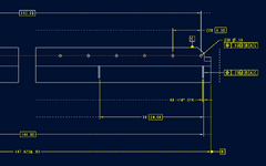
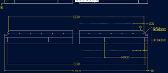
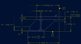
Can i use Position to locate an object on a weldment? See attached image. A is the bottom perpendicular surface.
My intent is to have all of my hole patterns and gussets symmetric to weldment centerline. I have a 5x 24 basic dimension doing the spacing of the gussets. I also added a 144" basic dimension that is overall width of the end gussets. Is that 144" dimension even needed? Does the 5x 24" dimension cover intent?
Thanks