greenimi, chez311, thank you for bringing reference to the thread about fig. 4-48.
I think that the idea of the arbitrary origin of the DRF in that figure as described by Belanger and axym in that thread is pretty close to what I described in my post today at 05:18 (with the difference that there are actually 2 "default" options for the origin, as described by Belanger - and I managed to count 3 somehow - don't ask).
I've been aware for a while that there is often more than one valid option for the location of the origin of the datum reference frame, but I thought that the
orientation of the DRF planes relative to the part is fairly meaningful for dimensioning because if the inspection department follows the default specification per Y14.5, then it is probably much more convenient when the basic dimensions are given normal/parallel to the planes of the DRF (at the directions of the X/Y/Z axes). But, perhaps someone may debunk this? It would be interesting to learn from others' knowledge and experience.
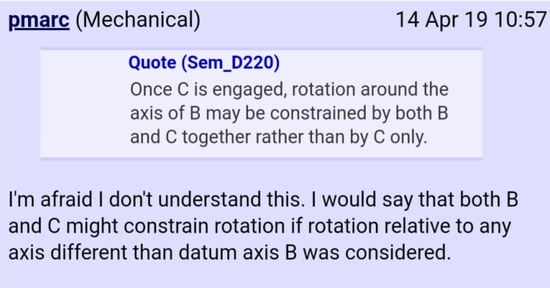
One thing that might be confusing (or even ambiguous?) about multiple options for the location of a datum reference frame is -which datum feature constrains which rotational degree of freedom. Recently in thread1103-451384 I posted the following image:
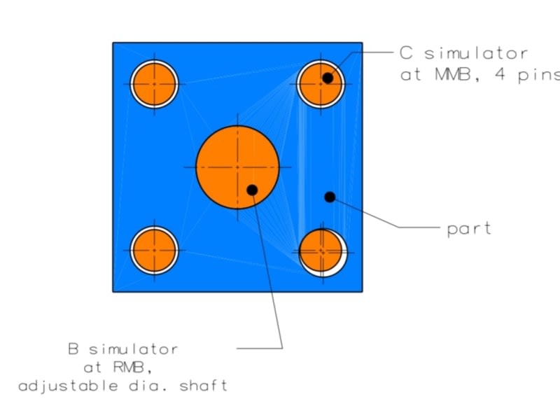
The blue is the as-produced part with the bottom right hole touching the MMB boundary and the orange are the datum feature simulators. Datum feature A is a face normal to the holes (either the shown or the hidden side in the view). If one establishes the datum reference frame per the standard specification (or should I say recommendation?), one of the axes of the DRF must coincide with datum axis B. In that case, as pmarc noted in that thread, it is clear that datum feature B only locates the part, and only datum feature C orients it. If some other arbitrary axis is chosen as the origin of the datum reference frame, such as one of the axes of the pattern of the 3 smaller holes produced more or less accurately, then it might appear as if for this specific produced geometry the rotation of the part relative to the DRF is constrained by B-C (together) rather than just by C tertiary.
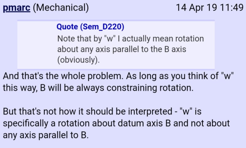
If the axis of the bottom right hole is chosen, than it might appear as datum feature B orients the part! The possibility to choose the DRF origin out of multiple axes led me to a misconception that the "w" rotation DOF is rotation about any axis parallel to any of the axes of the holes (designated Z for that matter). But only when the axis of the DRF is coincident with datum axis B it is clear that it is datum feature C that orients. I am thankful to pmarc for pointing it out for me, and that discussion led me to believe that the location of the DRF origin matters, and should be established per the specification in the standard. Here are some screenshots of that discussion:
The opinions expressed in this thread that the exact location and orientation of a DRF doesn't really matter and the referenced thread about fig. 4-48 leave me somewhat confused, at least for now. I would be thankful to anyone who can address this matter.