dtmbiz,
Modifiers placed in conjunction with datum feature references ([BSC] or otherwise) only modify the behavior of datum feature simulators relative to each other. Tolerance zones are always held in basic relationship to the theoretical datums, and their behavior is dictated by the type of tolerance zone (ie: Orientation tolerance dictates orientation is held but not location, Position tolerance dictates both location and orientation are held). The referenced sections of the standard, with the exception of fig 4-31, have nothing to do with the [BSC] modifier specifically in conjunction with datum feature references.
Instead of expanding on this further, I'll just answer Burunduk's question to show how the [BSC] modifier works.
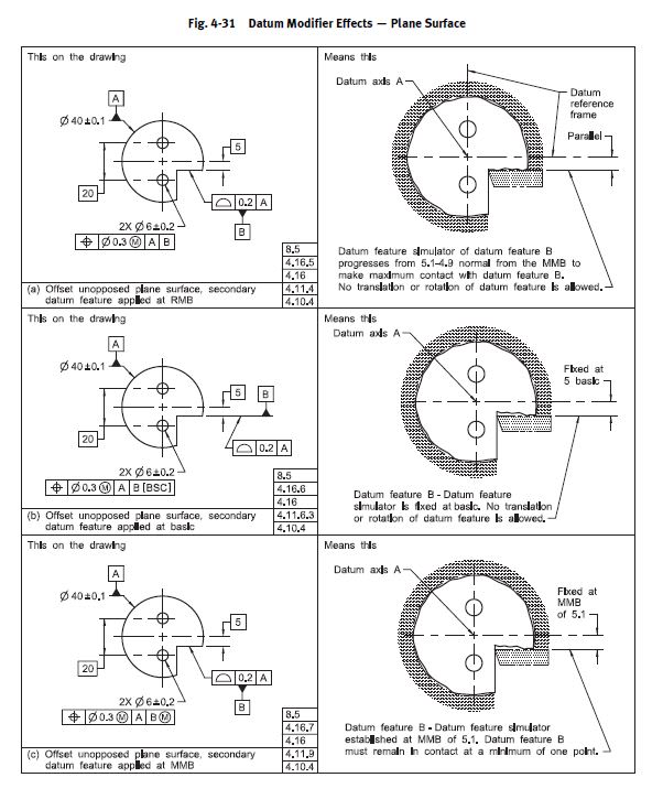
Considering fig. 4-31 that you posted above, illustrations (a) and (b), how would you describe the effect of the basic modifier on the tolerance zone of the 2 holes?
I am not sure how I would describe it myself, except that (b) is probably a more strict requirement. (a) allows some mobility of the B datum feature simulator, and indirectly also of the tolerance zones for the holes. Regardless in both (a) and (b) cases both location and orientation are fully controlled.
The bolded portion is correct, in both cases the requirement for basic location/orientation of the datum feature simulators is NOT overridden (as I said - can ONLY be done with customized DRF or datum translation). At first this may seem strange because in (a) B is allowed to progress and in (b) B is fixed. To understand this I think the 2018 version does a better job in defining this as when [BSC] is specified "the true geometric counterpart is defined by the basic dimensions of the true profile of the datum feature". In both (a) and (b) the
true profile of the datum feature simulator (true geometric counterpart) is fixed in basic orientation and location, however in (a) the simulator is allowed to be uniformly offset normal to the true profile within its profile tolerance which is shown as progression from 5.1-4.9 . In (b) this uniform offset (progression) is not allowed and the simulator is defined by the true profile.
A cone doesn't have size?
A cone is more similar to a plane than a cylinder
A cone isn't a FOS because it doesn't have a UAME ?
No modified definition of Y14.5 is required to reach these conclusions.
A cone doesn't have size? A unique actual value for size per ASME Y14.5.1-1994 is not defined for conical features.
A cone is more similar to a plane than a cylinder. This comes from the geometry involved not any definition in the standard. A conical primary datum feature at RMB can be simulated by a fixed simulator, similar to a planar feature. Not so with a cylindrical feature (RMB requires an expanding simulator).
A cone isn't a FOS because it doesn't have a UAME ? If we are to consider the definitions for RFOS/IFOSa/IFOSb the only one where a conical feature with a conical boundary/envelope MIGHT fit would be IFOSb (RFOS requires a "cylindrical or spherical surface, a circular element, and a set of two opposed parallel elements or opposed parallel surfaces" and IFOSa requires an envelope which is a "sphere, cylinder, or pair of parallel planes"). That still leaves the requirement that the feature must be "contain or be contained by" this conical envelope, which I have shown multiple times is not the case. Therefore a conical feature with a conical envelope satisfies NONE of the available definitions, written exactly per the standard, for RFOS, IFOSa, or IFOSb - therefore it is NOT a FOS.