Bojoka4052:
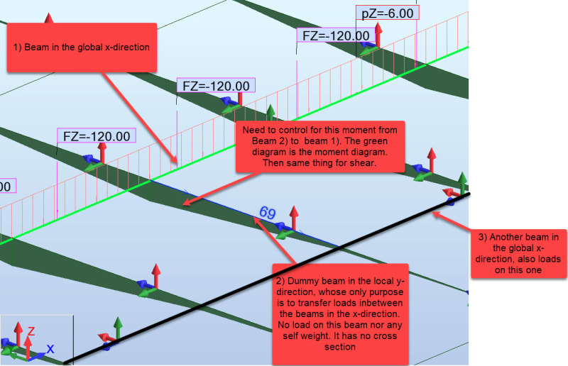
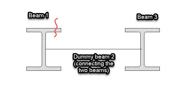
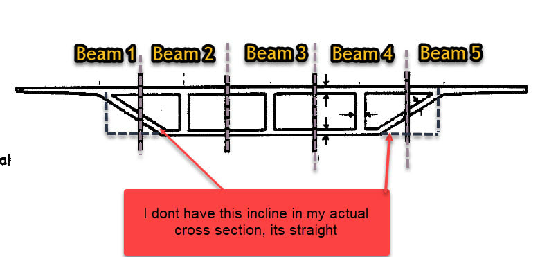
You claim to have modeled your structure correctly in your software, you claim to have included all the correct loadings in your model and then you model a continuous perpendicular spanning load distributing element (the deck slab) as discrete beam elements, at some spacing. All the while seeming to have no understanding or engineering knowledge of how this structure really works in the real world. You show a weird-assed moment diagram in the conc. slab/discrete, non-existent cross beam, no dimensions, no loads, no nothin, just some imaginary moments, and you show what appears to be a couple WF steel beams, with a string (or something) btwn. them, all absolutely contrary to the real world conditions. I think your model and your assumptions need some serious review and scrutiny. And, finally, like the effort involved in pulling teeth, seven or eight post later, you show a cross section of a bridge section which an experienced Structural Engineer would actually recognize and understand. So, the prior six or seven posts, all by knowledgeable and experienced Etips members were just guessing at what you had, and kinda a waste of their time, all for your lack of defining your problem properly/adequately, in the first place. Don’t use us/ETips as a crutch for your lack of real world engineering knowledge. You have to define your problem with enough meaningful engineering info., sketches and the like, so an experienced engineer understands what you are trying to do, or you are wasting everyone’s time.
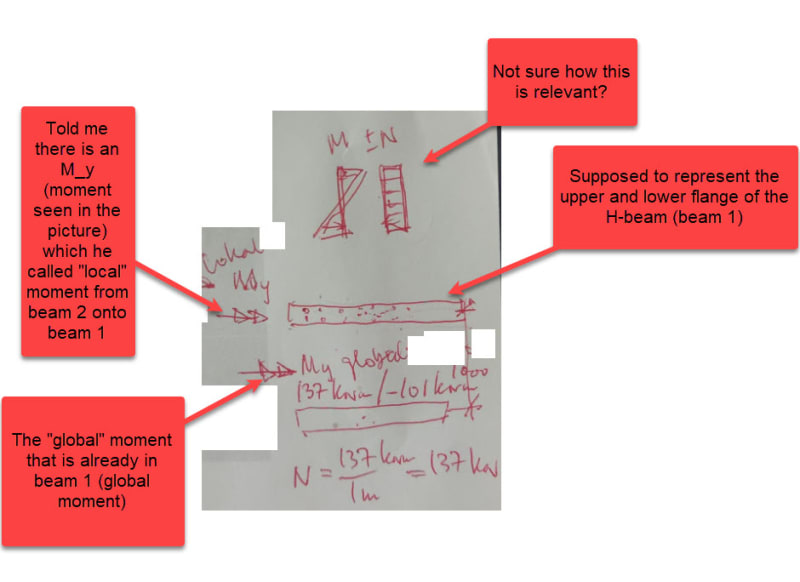
Take this problem back to your boss, and work it out, so he knows what you know and what you don’t know, so he can guide you accordingly, and keep you and the company out of serious trouble. I think what he is saying is that you have significant bending normal stresses, or shears, in the X & the Y directions in the slab, due to bending in the primary beam members and in the slab bending across the main beams respetively, and you should pay some attention to those combined stresses in the slab.