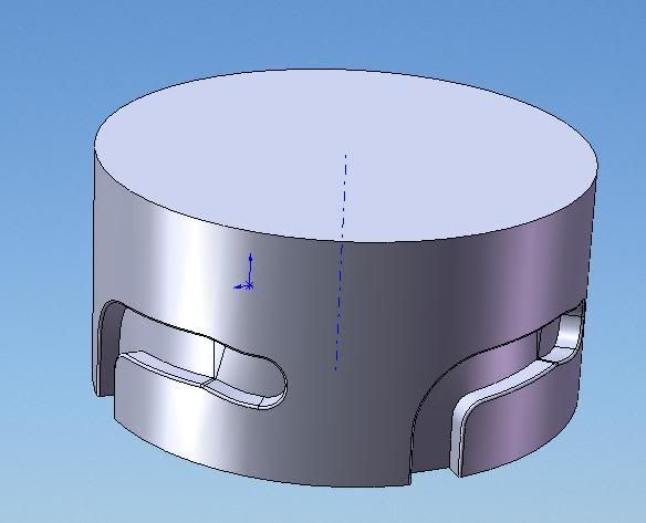
Maybe I'm a little late to the party here, and I have not read thru all the posts, but something just struck me looking at the image at the top of this thread - the image of the 'cup' with the external female bayonet mount undercuts. My idea might get in the way of any aeshtetic you need for the part, but I'll leave that judgement up to you.
In this thread here has been talk about multiple slides and/or moving cores to relieve the undercuts of the 'L' shaped bayonet feature. It looks like (upon quickly glancing thru the posts) that it has been assumed thus far that the orientation of your original part as shown at the beginning of this thread wants to be molded such that the parting line of the mold is parallel to the top or bottom of the part, and then to add additional tooling to achieve the (4) necessary undercuts on the outside of the part as shown in your original sketch.
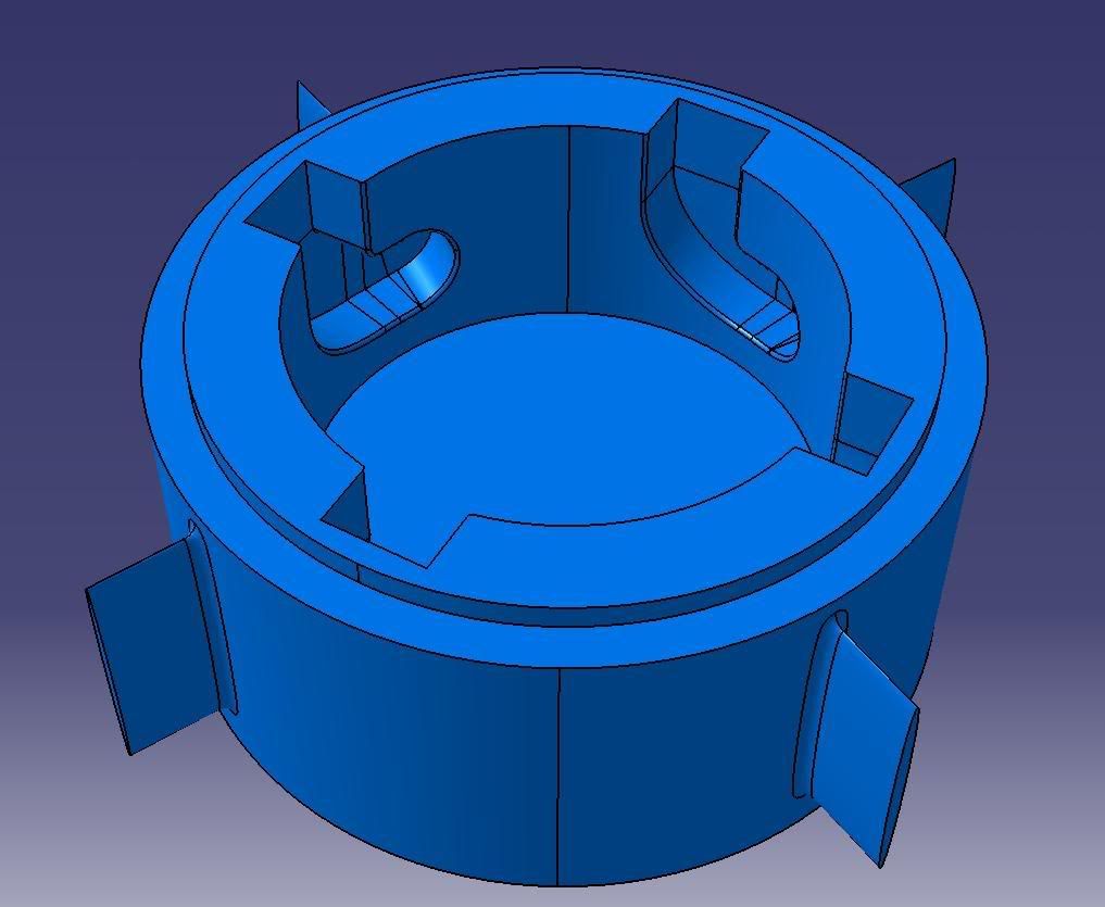
One alternative that will affect how the part looks on the outside of the 'cup' yet still retain bayonet funtionality might be to lay the 'cup' down in the mold such that ONLY ONE SIDE ACTION would be required to produce the inner round core of your part. As for the four 'bayonet' 'L' shaped features, two of them could be moulded without side actions as they could be located such that the natural draw of the mold would produce their geometry, and then the geometry of the other two female bayonet features that lie across the parting line could be modified so as to releive their undercuts. Even though material is releived from the two features that lie across the parting line, they could quite possibly still retain the functionality of the bayonet mount at those two locations. (Another words, the locking feature that is molded across the parting line would no longer be 'L' shaped as you originally depicted, but would end up sort of as a nearly flat surface in the area that receives the pin, and as a nearly flat radial groove in the area in which the pin is allowed to traverse.
Examining the concept a little deeper...If you've followed me thus far, and if I'm seeing your original sketch correctly, the two 'L' shaped bayonet pin tracks that are molded away from the parting line could retain what appears to be a pin-detent feature. The two detent features that would be molded at the parting line of the mold might be lost, but maybe once you up-end the 'cup' 90 degrees, you might find a way to include a detent at the parting line (by making one half of each groove smaller and offset slightly from the groove that is molded in the plate opposite the grooves parting line) if you truly needed four detent features.
I currently don't have any modeling program at hand, otherwise I'd produce the concept for you.
As a side note, on the blue model that appears above this post, you show four external wings...they would not mold well as skinny as you have them shown...I would recommend that you fatten them up to about 2/3 the thickness of your general wall thickness of the part.