SFCharlie (Computer),
I haven't followed WJE modelling recently but I know the accuracy of every mathematical model depends on the assumptions used. Rubbish in rubbish out.
I post the follow sketch to higlight some of the important considerations
I have shown three section of the deck in A, B and C. C and A were highly stressed laterally by the transverse tendons whereas Member 11/12 was unstressed in the same direction. Thus the interface is prone to crack when there is a major change in stresses in the components. These members were initially held tight together by the PT rods in 11. According to OSHA report 11 has no structural crack at the CJ prior to the bridge removal from the casting yard.
The CJ was seen open up (or cracked) after the bridge had been installed at its final position and the PT rod stress was removed. At this point 11 would have its highest compression load (less only the live load) and it could only hold its position if its joint with the deck did not break.
It can be said with certainty in any court of law that the joint in question had already failed structurally prior to the collpase and re-tightening of the PT rods. The following sketch shows the effects from the embedded items.
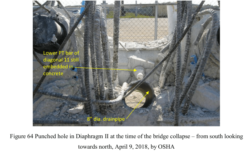
Prior to the collapse we know the CJ had cracked or the interface shifted horizontally. The failed components show the failure plane could include the horizontal CJ indicated by the orange dotted line, a vertical plane between the deck and the bottom of Member 12 (show in red dotted line) and two horizontal plane , in green dotted line on either face of 12) along the embedded 8" drain pipe's centreline. In transverse direction possibly two more vertical planes, on either face of 12, shown as B1 were contributing shear resistance against failure.
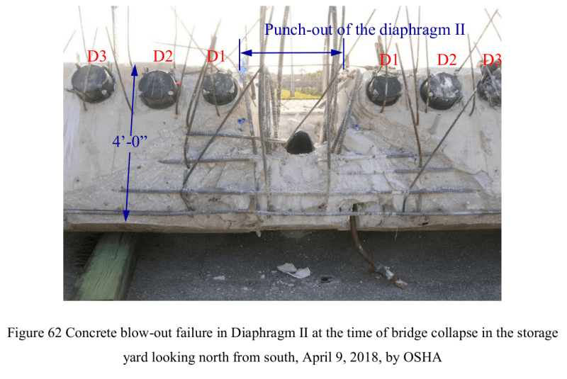
OSHA has called it a blow-out failure when the bridge collpased.
The shear resistance of concrete and the shear resistance of rebar across the above dotted line interfaces or plane are the main forces to hold the bridge together. Some enhanced shear resistance from the clamping action may be at play but not much in this failing mode.
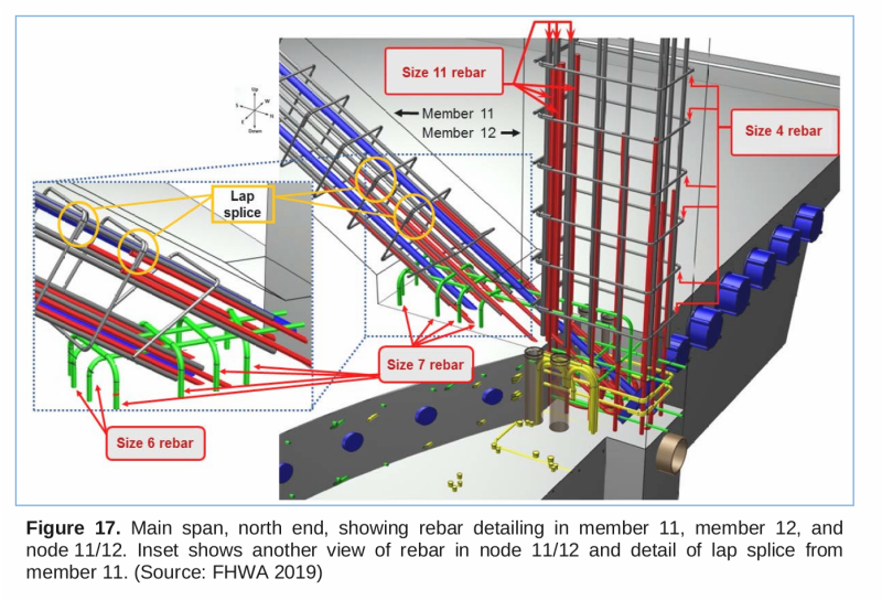
The design has a modest but not generous amount of shear steel across the CJ interface. At the deck interface with the front of 12 reinforcement is lacking because of the two PT rod anchors there plus the semi-circular cutout for the drainage pipe had left little room for passing the reinforcement through. The two sides bonding of 12 with the deck, Area maked B1, have been curtailed severely vertically by the 4x4" vertical sleeves and horizontally cut off by the presence of 8" drian pipe.
I have not gone through every steel bar to compute the capacity of this joint but it is a lot weaker than any drawing could reveal if the full set of embedded itmes were not included in the examonation.
Only looking at how little room availabe for inserting rebar so that it can have adequate development lengths, on both sides, then one realises how hopeless is the situation. If WJR could not find how this joint fails then its modeller has not enough practical knowledge of reinforced concrete in the field. If any rebar cannot be anchored adequately in both directions across an interface then that rebar should be written off structurally (for not able to realise its full material stress). In the OSHA report one can find a rich set of examples showing exposed bars with intact hooks and clean lengths which indicate the failures were by bonding and not shear.